
Page 158 - Process Equipment and Plant Design Principles and Practices by Subhabrata Ray Gargi Das
P. 158
5.10 Design illustration 155
Tick off heuristics – Hot Section
156°C 430.56 kW
CP = 8.28 104°C
3 E2
107.4 kW 1475.69 kW
175°C 170.18°C
CP = 22.3 104°C
13 E1 E3
N units = 4+3 = 7
243°C 2473.5 kW S = 7
CP = 29.1 158°C = S-1 = 6
16 E4 N min
ΔH Total = 3780 121°C
121°C 121°C kW
E4 14
1306.5 kW
466.28 kW 178.36°C 121°C H1 175°C
182°C CP = 128.1
H2 E2 2
94°C
106°C CP = 8.95
E1 4
107.4 kW 94°C
122°C 121.67°C CP = 53.34
H3 E3 19
Tick off heuristics – Cold Section
104°C 529.92 kW
CP = 8.28 40°C
3 C1
N = 3
units
104°C 295.35 kW S = 4
CP = 22.3 90.76°C 1131.85 kW 40°C N min = S-1 = 3
13 E5 C2
61°C
94°C CP = 8.95
E5 4
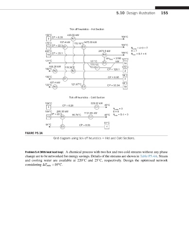
FIGURE P5.3A
Grid diagram using tick off heuristics e Hot and Cold Sections.
Problem 5.4 (With heat load loop). A chemical process with two hot and two cold streams without any phase
change are to be networked for energy savings. Details of the streams are shown in Table P5.4A. Steam
and cooling water are available at 220 C and 25 C, respectively. Design the optimised network
o
considering DT min ¼10 C.