
Page 154 - Process Equipment and Plant Design Principles and Practices by Subhabrata Ray Gargi Das
P. 154
5.10 Design illustration 151
Network required only hot utility - Maximum energy recovery
- Minimum no. of units.
300°C
CP = 0.2 230°C
4 E3
300°C
CP = 0.3 40°C
5 E2
200°C
CP = 0.1 30°C
6 E1
17 kW 140°C
230°C 225°C CP = 0.2
H1 E1 1
20°C
1 kW 180°C CP = 0.4875
E2 2
78 kW
CP = 0.3125
H E3
36 kW 14 kW
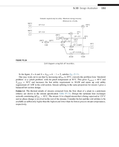
FIGURE P5.2A
Grid diagram using tick off heuristics.
In the figure, S ¼ 6 and N ¼ N min ¼ 6 e 1 ¼ 5, satisfies Eq. (5.13).
One may work out to see that by increasing DT min to 20 C, converts the problem from ‘threshold
problem’ to a ‘pinch problem’ with the pinch temperature at 30 C. This gives T h,pinch ¼ 40 C and
T c,pinch ¼ 30 C and increases the hot utility requirement to 38 kW and opens up cold utility
requirement of 1 kW in the cold section. Stream splitting in the same proportion for stream 2 gives a
balanced hot section design.
Problem 5.3. The thermal details of streams extracted from the flow sheet of a plant in a petroleum
refinery are shown in the stream specification Table P5.3A. Design the optimum heat exchanger
network considering DT min ¼ 10 C. The stream 14 is a liquid stream that is being vaporised at 121 C
and no phase change is involved in the rest of the streams. Consider the hot and the cold utilities to be
available at sufficiently higher than the highest and lower than the lowest process stream temperatures,
respectively.