
Page 149 - Process Equipment and Plant Design Principles and Practices by Subhabrata Ray Gargi Das
P. 149
146 Chapter 5 Heat exchanger network analysis
Tick off heuristics – Cold Section
150°C 220 kW
40°C
1 C
150°C 101∙25°C 48∙75°C 35 kW
40°C
2 C
195 210
kW kW 60°C
130°C
3
30°C
105°C
4
= 4 (Eq. 5.13)
S = 4+1 = 5, N min
= 4
N actual
Tick off heuristics – Hot Section
180°C 150°C
1
90 kW 60 kW 130°C
180°C 150°C
H 3
S = 2+1=3, N min = 2 (Eq. 5.13)
N = 2
actual
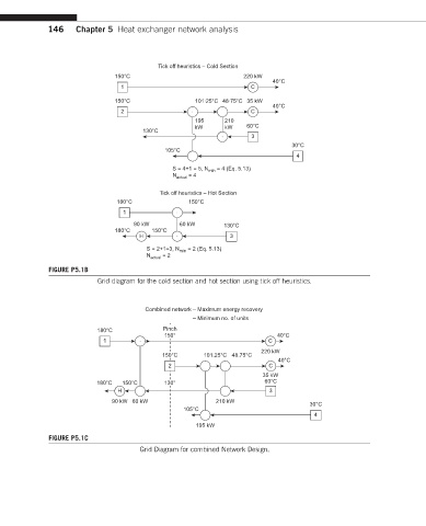
FIGURE P5.1B
Grid diagram for the cold section and hot section using tick off heuristics.
Combined network – Maximum energy recovery
– Minimum no. of units
180°C Pinch
150° 40°C
1 C
220 kW
150°C 101.25°C 48.75°C
40°C
2 C
35 kW
180°C 150°C 130° 60°C
H 3
90 kW 60 kW 210 kW
30°C
105°C
4
195 kW
FIGURE P5.1C
Grid Diagram for combined Network Design.