
Page 150 - Process Equipment and Plant Design Principles and Practices by Subhabrata Ray Gargi Das
P. 150
5.10 Design illustration 147
One may note that for the 210 kW HE between stream 2 and 4 in the cold section, DT min ¼ 20 Cis
not respected. However, this exchanger operates away from the pinch temperature and the temperature
difference is above 10 C, which is acceptable for such services.
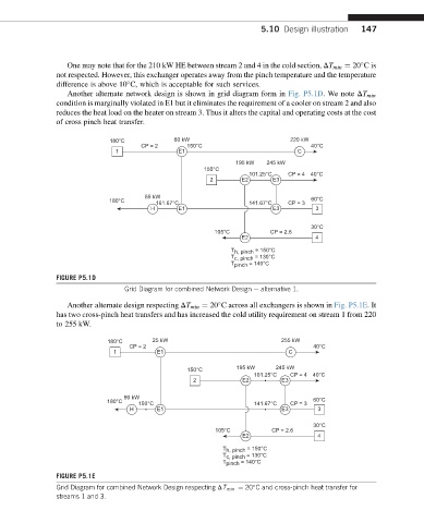
Another alternate network design is shown in grid diagram form in Fig. P5.1D. We note DT min
condition is marginally violated in E1 but it eliminates the requirement of a cooler on stream 2 and also
reduces the heat load on the heater on stream 3. Thus it alters the capital and operating costs at the cost
of cross pinch heat transfer.
180°C 60 kW 220 kW
CP = 2 150°C 40°C
1 E1 C
195 kW 245 kW
150°C
101.25°C CP = 4 40°C
2 E2 E3
55 kW 60°C
180°C 161.67°C 141.67°C CP = 3
H E1 E3 3
30°C
105°C CP = 2.6
E2 4
T h, pinch = 150°C
T c, pinch = 130°C
T pinch = 140°C
FIGURE P5.1D
Grid Diagram for combined Network Design e alternative 1.
Another alternate design respecting DT min ¼ 20 C across all exchangers is shown in Fig. P5.1E.It
has two cross-pinch heat transfers and has increased the cold utility requirement on stream 1 from 220
to 255 kW.
180°C 25 kW 255 kW
CP = 2 40°C
1 E1 C
150°C 195 kW 245 kW
101.25°C CP = 4 40°C
2 E2 E3
90 kW
180°C 150°C 141.67°C CP = 3 60°C
H E1 E3 3
30°C
105°C CP = 2.6
E2 4
T h, pinch = 150°C
T c, pinch = 130°C
T pinch = 140°C
FIGURE P5.1E
Grid Diagram for combined Network Design respecting DT min ¼ 20 C and cross-pinch heat transfer for
streams 1 and 3.