
Page 162 - Process Equipment and Plant Design Principles and Practices by Subhabrata Ray Gargi Das
P. 162
Further reading 159
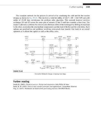
The complete network for the process is arrived at by combining the cold and the hot section
designs as shown in Fig. P5.4C. This involves a total hot utility of (22.5 þ 40 ¼) 62.5 kW and cold
utility of 45 kW that corroborates the problem table algorithm. This network however involves
exchanger E4 and E2 across the same pair of streams (2 and 3) and thus contains a heat loop. The
reader is advised to continue the exercise and eliminate either of the exchanger by shifting its heat load
to the other, recalculate the intermediate temperatures and the load of the hot and the cold utility. Such
options are practised in real problems involving cross-pinch heat transfer that leads to an overall
optimum as it affects the capital as well as the utility costs.
170°C 200 kW 30 kW 45 kW
90°C 78°C 60°C
1 E3 E1 C1
150°C 60 kW 60 kW
90°C 30°C
2 E4 E2
22.5 kW 20°C
135°C 80°C 60°C
H1 E4 E1 E2 3
Heat load loop
40 kW 80°C
140°C 130°C
H2 E3 4
Hu = 62.5 kW; Cu = 45 kW
T c, pinch = 80°C, T pinch = 85°C, T h, = 90°C
FIGURE P5.4C
Complete Network Design showing heat loop.
Further reading
Smith, R. (2005). Chemical process: Design and integration. John Wiley & Sons.
Serth, R. W. (2007). Process heat transfer principles and applications. Amsterdam: Elsevier.
Nag, A. (2015). Distillation & hydrocarbon processing practices. PennWell Books.