
Page 173 - Process Equipment and Plant Design Principles and Practices by Subhabrata Ray Gargi Das
P. 173
6.3 Evaporator types 171
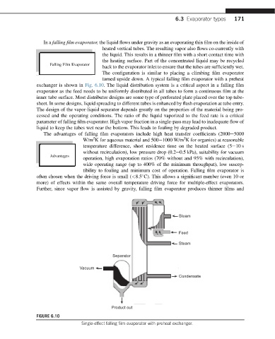
In a falling film evaporator, the liquid flows under gravity as an evaporating thin film on the inside of
heated vertical tubes. The resulting vapor also flows co-currently with
the liquid. This results in a thinner film with a short contact time with
the heating surface. Part of the concentrated liquid may be recycled
Falling Film Evaporator
back to the evaporator inlet to ensure that the tubes are sufficiently wet.
The configuration is similar to placing a climbing film evaporator
turned upside down. A typical falling film evaporator with a preheat
exchanger is shown in Fig. 6.10. The liquid distribution system is a critical aspect in a falling film
evaporator as the feed needs to be uniformly distributed in all tubes to form a continuous film at the
inner tube surface. Most distributor designs are some type of perforated plate placed over the top tube-
sheet. In some designs, liquid spreading to different tubes is enhanced by flash evaporation at tube entry.
The design of the vapor-liquid separator depends greatly on the properties of the material being pro-
cessed and the operating conditions. The ratio of the liquid vaporized to the feed rate is a critical
parameter of falling film evaporator. High vapor fraction in a single-pass may lead to inadequate flow of
liquid to keep the tubes wet near the bottom. This leads to fouling by degraded product.
The advantages of falling film evaporators include high heat transfer coefficients (2000e5000
2
2
W/m K for aqueous material and 500e1000 W/m K for organics) at reasonable
temperature difference, short residence time on the heated surface (5e10 s
without recirculation), low pressure drop (0.2e0.5 kPa), suitability for vacuum
Advantages
operation, high evaporation ratios (70% without and 95% with recirculation),
wide operating range (up to 400% of the minimum throughput), low suscep-
tibility to fouling and minimum cost of operation. Falling film evaporator is
often chosen when the driving force is small (<8.5 C). This allows a significant number (even 10 or
more) of effects within the same overall temperature driving force for multiple-effect evaporators.
Further, since vapor flow is assisted by gravity, falling film evaporator produces thinner films and
Steam
Feed
Steam
Separator
Vacuum
Condensate
Product out
FIGURE 6.10
Single-effect falling film evaporator with preheat exchanger.