
Page 226 - Process Equipment and Plant Design Principles and Practices by Subhabrata Ray Gargi Das
P. 226
224 Chapter 7 Industrial cooling systems
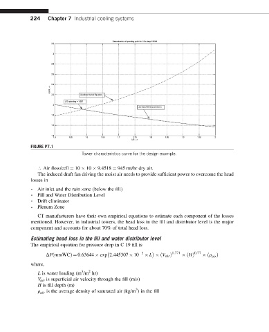
FIGURE P7.1
Tower characteristics curve for the design example.
r Air flow/cell ¼ 10 10 9.4518 ¼ 945 mt/hr dry air.
The induced draft fan driving the moist air needs to provide sufficient power to overcome the head
losses in
- Air inlet and the rain zone (below the fill)
- Fill and Water Distribution Level
- Drift eliminator
- Plenum Zone
CT manufacturers have their own empirical equations to estimate each component of the losses
mentioned. However, in industrial towers, the head loss in the fill and distributor level is the major
component and accounts for about 70% of total head loss.
Estimating head loss in the fill and water distributor level
The empirical equation for pressure drop in C 19 fill is
3 1:771 0:77
DPðmmWCÞ¼ 0:63644 exp 2:445307 10 L ðV air Þ ðHÞ ðr Þ
air
where,
3
2
L is water loading (m /m hr)
V air is superficial air velocity through the fill (m/s)
H is fill depth (m)
3
r air is the average density of saturated air (kg/m ) in the fill