
Page 273 - Process Equipment and Plant Design Principles and Practices by Subhabrata Ray Gargi Das
P. 273
274 Chapter 10 Absorption and stripping
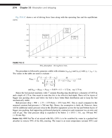
Fig. P10.1C shows a set of driving force lines along with the operating line and the equilibrium
curve.
0.12
Driving
0.1
force
line(s)
0.08
Operating
line Equilibrium
curve
y 0.06
0.04
0.02
0
0 0.01 0.02 0.03 0.04 0.05 0.06 0.07 0.08
x
FIGURE P10.1C
NH 3 absorption - driving force lines.
The procedure is followed to generate a table with columns (x op ,y op ) and (x i ,y i )with y 2 < y op < y 1 .
The values in the table are used to evaluate e
Z y1
ð1 y i Þ 1 y op dy
¼ 4:1
8 9
N TOG ¼
y2 < = ð1 y i Þ y op y i
ð1 y i Þ
ln
: 1 y op ;
and h bed ¼ H TOG N TOG ¼ 0:419 4:1 ¼ 1.72 m; say 1.75 m.
Hence the bed packed randomly with 1 ceramic Raschig ring should have a diameter of 0.835 m
00
and a depth of 1.75 m. One needs to note that this is the effective bed depth. There will be layers of
bigger size packing above and below the bed to have better fluid distribution and to keep the bed
mechanically stable.
Bed pressure drop ¼ 900 1.75 ¼ 1575 Pa/m ¼ 155.5 mm WC. This is small compared to the
assumed constant bed pressure (w760 mm Hg). Hence, the assumption is fairly ok. However, there
will be additional minor pressure drop in the absorber equipment across the top and bottom layers of
bigger size packing, bed supporting perforated plate/grid, contraction and expansion loss at entry and
exit of gas. The total pressure drop is expected to be below 2 155.5 ¼ 311, say 350 mm WC
(w26 mm Hg).
3
Problem 10.2. 4000 Nm /hr of air mixed with SO 2 (10%) is to be scrubbed by water in a packed bed
o
absorber to remove 95% of the SO 2 entering. The water is at room temperature (around 30 C) and