
Page 147 - Process Modelling and Simulation With Finite Element Methods
P. 147
134 Process Modelling and Simulation with Finite Element Methods
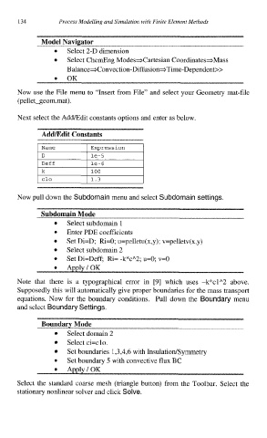
Model Navigator
Select 2-D dimension
Select ChemEng Modesacartesian CoordinatesaMass
B alanceaConvection-Diffusion+Time-Dependent>>
OK
Now use the File menu to “Insert from File” and select your Geometry mat-file
(pellet-geom.mat).
Next select the AddIEdit constants options and enter as below.
Admdit Constants
I Name I Expression I
D le-5
I
<
I 100
Ik
1.3
Now pull down the Subdomain menu and select Subdomain settings.
Subdomain Mode
Select subdomain 1
Enter PDE coefficients
Set Di=D; Ri=O; u=pelletu(x,y); v=pelletv(x,y)
Select subdomain 2
Set Di=Deff; Ri= -k*cA2; u=O; v=O
Note that there is a typographical error in [9] which uses -k*clA2 above.
Supposedly this will automatically give proper boundaries for the mass transport
equations. Now for the boundary conditions. Pull down the Boundary menu
and select Boundary Settings.
Boundarv Mode
Select domain 2
Select ci=clo.
Set boundaries 1,3,4,6 with InsulatiodSymmetry
Set boundary 5 with convective flux BC
0
Select the standard coarse mesh (triangle button) from the Toolbar. Select the
stationary nonlinear solver and click Solve.