
Page 251 - Process Modelling and Simulation With Finite Element Methods
P. 251
238 Proczss Modelling and Simulation with Finite Element Methods
I
O! Od 06 09 O! 04 06 1
vcaralcoordioatc vcamlcoodmtc E O5
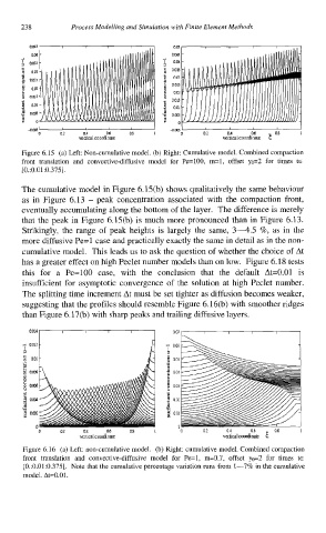
Figure 6.15 (a) Left: Non-cumulative model. (b) Right: Cumulative model. Combined compaction
front translation and convective-diffusive model for Pe=100, m=l, offset yo=2 for times tE
[0.:0.01:0.375 1.
The cumulative model in Figure 6.15(b) shows qualitatively the same behaviour
as in Figure 6.13 - peak concentration associated with the compaction front,
eventually accumulating along the bottom of the layer. The difference is merely
that the peak in Figure 6.15(b) is much more pronounced than in Figure 6.13.
Strikingly, the range of peak heights is largely the same, 3-4.5 %, as in the
more diffusive Pe=l case and practically exactly the same in detail as in the non-
cumulative model. This leads us to ask the question of whether the choice of At
has a greater effect on high Peclet number models than on low. Figure 6.18 tests
this for a Pe=100 case, with the conclusion that the default At=0.01 is
insufficient for asymptotic convergence of the solution at high Peclet number.
The splitting time increment At must be set tighter as diffusion becomes weaker,
suggesting that the profiles should resemble Figure 6.16(b) with smoother ridges
than Figure 6.17(b) with sharp peaks and trailing diffusive layers.
0.014 0 07
A ow - 006
I I
: 0.01 8 a05
1 0.m oa4
Y 8
E om 6 am
i
j 0.m 4 a02
B
o.m! oai
0 a
0 0.2 0.4 Oh 03 i 0 02 a4 06 08 I
vcrticai condinate veitica~ cmidinate F.
Figure 6.16 (a) Left: non-cumulative model. (b) Right: cumulative model. Combined compaction
front translation and convective-diffusive model for Pe=l, m=0.7, offset yo=2 for times tg
[0.:0.01:0.375]. Note that the cumulative percentage variation runs from I-7% in the cumulative
model. At=0.01.