
Page 265 - Process Modelling and Simulation With Finite Element Methods
P. 265
252 Process Modelling and Simulation with Finite Element Methods
El, edit center to (0.6,0.2) and set both semi axes to 0.1
E2, edit center to (-0.4,0.7) and set both semi axes to 0.1
E3, edit center to (0.4,-0.5) and set both semi axes to 0.1
E4, edit center to (-0.8,-0.2) and set both semi axes to 0.1
Create a composite “Swiss cheese” object COl=COl-EI-E2-E3-E4
Re-draw ellipses El-E4 as above, to fill the “wholes” with four
domains.
Apply
OK
The rough entry of the vertices is corrected by the ability to edit the analytical
geometry features for graphical objects. Our closed curved is not quite a circle,
but then neither are ECT systems once the electrodes are installed. The 12
segments of the boundary can be assigned individual boundary conditions and
also are domains available for post processing. Now for the boundary conditions.
Pull down the Boundary menu and select Boundary Settings.
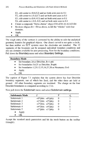
Boundary Mode
Set boundary 24 as Dirichlet, R=l-phi
Set boundaries 5,6,21 as Dirichlet, R=phi
Set boundaries 1,2,9,12,15,16,27,28 as Neumann, G=O
APPlY
OK
The caption of Figure 7.1 explains that the system above has four Dirichlet
boundary segments, one of which has fired, and the other three are held at
ground. All other boundary segments are insulated. The charge on the four
Dirichlet boundaries is computed according to (7.4).
Now pull down the Subdomain menu and select Subdomain settings.
Subdomain Mode r F d,
Subdomain 1 -eO*phix -eO*phiy 0 1
Subdomain 2 -e2*phix -e2*phiy 0 1
Subdomain 3 -e3*phix -e3*phiy 0 1
Subdomain 4 -e4*phix -e4*phiy 0 1
Subdomain 5 -el*phix -el*phiy 0 1
Apply
OK
Accept the standard mesh parameters and hit the mesh button on the toolbar
(triangle).