
Page 336 - Process Modelling and Simulation With Finite Element Methods
P. 336
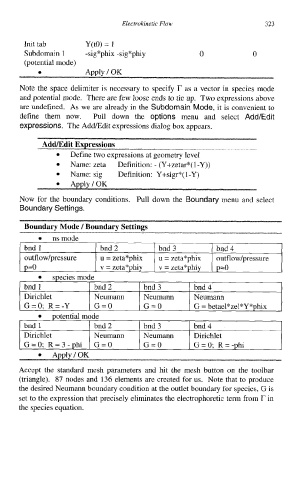
Electrokinetic Flow                 323

           Init tab       Y(tO) = 1
           Subdomain 1    -sig*phix -sig*phiy          0             0
           (potential mode)
              0           Apply I OK

         Note the space delimiter is necessary to specify T  as a vector in species mode
         and potential mode.  There are few loose ends to tie up.  Two expressions above
         are undefined. As we are already in the Subdomain Mode, it is convenient to
         define them now.  Pull down the options menu and select Add/Edit
         expressions.  The Add/Edit expressions dialog box appears.


         Now for the boundary cconditions.
         Boundary Settings.


           bnd 1              bnd 2          bnd 3          bnd 4
           outflowtpressure   u = zeta*phix   u = zeta*phix   outflowtpressure
           p=o                v = zeta*phiy   v = zeta*phiy   p=o

           bnd 1             bnd 2       bnd 3        bnd 4
           Dirichlet         Neumann     Neumann      Neumann
           G=0; R=-Y         G=O         G=O          G = betael*zel*Y*phix

           bnd 1           1  bnd2      1  bnd3      I  bnd4
           Dirichlet       I  Neumann  I  Neumann    1  Dirichlet
          I  G=0; R=3-phi  I  G=O       I G=O        1  G=O;  R= -phi


         Accept  the  standard mesh  parameters  and  hit  the  mesh  button  on  the  toolbar
          (triangle).  87 nodes and  136 elements are created for us.  Note that to produce
         the desired Neumann boundary condition at the outlet boundary for species, G is
          set to the expression that precisely eliminates the electrophoretic term from r in
          the species equation.