
Page 341 - Process Modelling and Simulation With Finite Element Methods
P. 341
328 Process Modelling and Simulation with Finite Element Methods
betael*zel*Y*p h ix
0
-0 2
-0 4
x -
L
P -0 6
z
N
i
: -08
I
II
(Y
-1
-1 2
-1 4 I
01 02 03 04 05 06 07 08 09 1
Arc Length
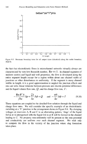
Figure 9.5 Neumann boundary term for all output times (identical) along the outlet boundary
(bnd 4).
the fact that electrokinetic flows in microchannel networks virtually always are
characterized by very low Reynolds number, Re << 1. In channel segments of
uniform section and liquid and wall properties, the flow is developed along the
entire segment length except for a region within about one channel width of
junctions or other disturbances to uniformity. If the segment is many channel
widths in length, it is a good approximation to neglect the junction effects and
one can write linear relations between pressure and electric potential differences
and the liquid volume flow rate, Q , and the charge flow rate, Z :
ReR2A @ OA
- Ap+-A$=Q and --A$=Z (9.10)
fAs As As
These equations are coupled to the detailed flow solution through the liquid and
charge flow rates. We will consider the specific example of an electrokinetic
switching at a ‘Y’ junction in the arrangement shown in Figure 9.6. By changing
voltages at reservoirs A, B and C in an alternating pattern, ‘slugs’ of the liquid
fed in at A interspersed with the liquid fed in at B will be formed in the channel
leading to C. No property non-uniformity will be present so the zeta potential
and conductivity are uniform over each channel segment. We wish only
to compute the flow in the vicinity of the junction where slug formation
takes place.