
Page 344 - Process Modelling and Simulation With Finite Element Methods
P. 344
Electrokinetic Flow 33 1
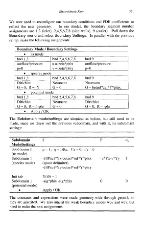
We now need to reconfigure our boundary conditions and PDE coefficients to
reflect the new geometry. In our model, the boundary segment number
assignments are 1,3 (inlet), 2,4,5,6,7,8 (side walls), 9 (outlet),. Pull down the
Boundary menu and select Boundary Settings. In parallel with the previous
set up, make the following assignments:
bnd 1,3 bnd 2,4,5,6,7,8 bnd 9
outflowlpressure u = zeta*phix outflowlpressure
p=o v = zeta*phiy p=o
species mode
bnd 1,3 bnd 2,4,5,6,7,8 bnd 9
Dirichlet Neumann Neumann
G=0; R=-Y G=O G = betael*zel*Y*phix
potential mode
I bnd 1,3 I bnd2,4,5,6,7,8 I bnd9 1
Dirichlet Neumann Dirichlet
G=0; R=5-phi G=O G=O; R= -phi
The Subdomain mode/settings are identical as before, but still need to be
made, since we threw out the previous subdomain, and with it, its subdomain
settings:
Subdomain r F da
Modelsettings
Subdomain 1 p=l; q=l/Re; Fx=O; Fy=O
(ns mode)
Subdomain 1 -( l/Pec)*Yx-betael*zel*Y*phix -u*Yx-v*Yy 1
(species mode) (space delimiter)
-( l/Pec)*Yy-betael*zel*Y *phiy
Init tab Y(t0) = 1
Subdomain 1 -sig*phix -sig*phiy 0 0
(potential mode)
0 Apply I OK
The constants and expressions were made geometry-wide through geoml , so
they are inherited. We also inherit the weak boundary modes wcu and wcv, but
need to make the new assignments.