
Page 59 - Process Modelling and Simulation With Finite Element Methods
P. 59
46 Process Modelling and Simulation with Finite Element Methods
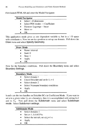
First launch FEMLAB and enter the Model Navigator:
Model Navigator
0 Select 1-D dimension
0 Select PDE modes + Coefficient
Element: Lagrange - linear
More >>
0
OK
This application mode gives us one dependent variable u, but in a 1-D space
with coordinate x. Now we are in a position to set up our domain. Pull down the
Draw menu and select Specify Geometry.
Draw Mode
Name: interval
Start: 0
stop: 1
Apply
OK
0
Now for the boundary conditions. Pull down the Boundary menu and select
Boundary Settings.
Boundary Mode
Select domain 1
Check Dirichlet and set h=l; r=l
Select domain 2
Select Neumann boundary conditions
Apply
OK
h and r are the two handles on Dirichlet BCs in Coefficient Mode. If you want to
set u to a given value UO on a boundary, then it is accomplished with setting h=l
and r= Uo. Now pull down the Subdomain menu and select Subdomain
mode. Select Subdomain settings.
Subdomain Mode
Select domains 1
Set c=-1; f=O.S33*u
Select the init tab; set u(h)=l-x
Apply
OK