
Page 55 - Process Modelling and Simulation With Finite Element Methods
P. 55
42 Process Modelling and Simulation with Finite Element Methods
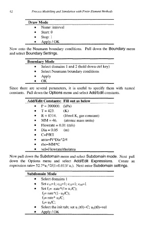
Draw Mode
Name: interval
0 Start: 0
stop: 1
Now onto the Neumann boundary conditions. Pull down the Boundary menu
and select Boundary Settings.
Boundary Mode
Select domains 1 and 2 (hold down ctrl key)
Select Neumann boundary conditions
Apply
OK
Since there are several parameters, it is useful to specify them with named
constants. Pull down the Options menu and select Add/Edit constants.
AddEdit Constants: Fill out as below
P=200000. (kPa)
T=423. (K)
R = 8314. (J/mol K, gas constant)
MM = 46, (atomic mass units)
0
Flowrate = 0.01 (m/s)
Dia=0.05 (m)
C=P/RT
area=Pi*Dia*2/4
rho=MM*C
vel=Flowrate/rho/area
Now pull down the Subdomain menu and select Subdomain mode. Next pull
down the Options menu and select Add/Edit Expressions. Create an
expression rate= 52.7*uIA2/( 1+0.013/ u,). Next enter Subdomain settings.
Subdomain Mode
Select domains 1
Set c,l=l; cz2=l; C33=1; C44=1
Set fl= -rate*(l+ ul/C);
f2= rate*( 1- uz/C);
f3= rate* u3/C;
f4= u3/c;
Select the init tab; set ul(tO)=C; u3(t0)=vel
Apply/OK