
Page 162 - Process simulation and control using Aspen
P. 162
ASPEN PLUS SIMULATION OF EHSTILLATIQM MODELS 149
LIGHTS <
WATER
STMl
sir,-
STM2
BOT
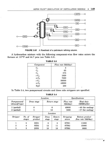
FIGURE 3.61 A flowsheet of a petroleum refining column.
A hydrocarbon mixture with the following component-wise flow rates enters the
furnace at 1170F and 44.7 psia (see Table 3.3).
TABLE 3.3
Component Flow rate (bbl/day)
Ci 3
c2 65
C3 575
i-C 1820
4
«-c 7500
4
i-C 30000
5
n-C 5 42000
H2O 250
In Table 3.4, two pumparound circuits and three side strippers are specified.
TABLE 3.4
Loeatum Specifications
Pumparound Draw stage Return stage Flow rate Heat duty
(drawoff type) (bbl/day) (MMBtu/hr)
1 (partial) 8 6 49000 - 40 (for cooling)
2 (partial) 1 12 1000 - 17 (for cooling)
Location
Stripper No. of Stripper Draw Return Stripping Bottom product
stages product stage stage steam flow rate (bbl/day)
1 5 SID1 6 5 STMl 11000
2 4 SID2 12 11 STM2 15000
3 3 SID3 19 18 STM3 8000
1