Page 16 - Radar Technology Encyclopedia
P. 16

6     accuracy of radar measurement, fundamental                 accuracy of sequential lobing, fundamental


           estimated angle, the  higher  the  angular measurement  accu-  get, is limited by thermal noise, and is measured by the ran-
           racy. SAL                                            dom noise error component s q :
           Ref.: Skolnik (1980), pp. 400–411; Shirman (1981), pp. 200–205; Leonov         q 3
              (1988), p. 25.                                                     s =  -----------------------------
                                                                                  q
                                                                                            ¤
                                                                                         (
                                                                                      k 2 EN )
                                                                                              0
           The  fundamental accuracy of monopulse  is achieved by
           comparison of signal amplitudes in  beams formed simulta-  where q  is the one-way half-power beamwidth, k is a pattern
                                                                      3
           neously (monopulse estimation or simultaneous lobing) per-  slope constant, and  E/N   is the applicable  signal-to-noise
                                                                                     0
           mits  the radar to approach the  fundamental accuracy limit  energy ratio. The different scanning options lead to different
           given by                                             values of k and E/N .
                                                                                0
                                                                    For the case of continuous (linear or sector) scanning, the
                                     q 3
                            s =  ---------------------------------  slope constant becomes k  = 1.66 and the energy ratio is that
                             q                                                       p
                                     (
                                       ¤
                                 k  2 EN )
                                 m       0                      of n pulses received with the on-axis ratio (S/N)  divided by a
                                                                                                      m
           where k   @ 1.6 is the monopulse  slope  constant and  E/  beamshape loss, L  = 1.33.
                                                                               p
                  m
           N =2n(S/N) is the total energy ratio for a target on the sum  For a step-scanned beam, the slope constant is given by
                      m
            0
           beam axis. When the target is displaced from the axis, the                      dG ¤(  G )
                                                                                     df
                                                                                              2
                                                                                                  1
           error will increase for two reasons: (a) the energy ratio in the    k =  --------------------- =  --------------------------
                                                                                   (
                                                                                               ¤
                                                                                             (
                                                                                     ¤
           sum channel will  decrease,  and (b) a second component  of            d qq )    d qq )
                                                                                       3
                                                                                                 3
           error, caused by noise in the normalization process (by which
                                                                where f is the voltage pattern of the beam, and G  and G  are
                                                                                                       1
                                                                                                              2
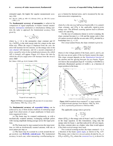
           D/S is formed), will appear. Figure A13 shows the ratio by
                                                                the one-way power gains of the two beams nearest the target.
           which the off-axis target error will increase from the on-axis
                                                                This slope constant depends on the illumination function of
           error. DKB
                                                                the antenna and the spacing between the two beams. Figure
           Ref.: Barton (1969), pp. 24, 43; Skolnik (1990).     A14 shows the normalized slope K¢ = k(l/Lq ) = k/0.886 for a
                                                                                                    3
                  3                                             uniformly illuminated aperture of width L, as a function of
                            2-way, k  = 2.0                     target position in the beam.
                                  m
                 2.5
                           2-way, k  = 1.6
                                 m
                        1-way, k  = 2.0
               s(q)/s(0)  1.5 2  m
                  1
                                        1-way, k  = 1.6
                                              m
                    1-way, without
                 0.5
                    normalization error
                  0
                    0     0.1   0.2    0.3    0.4    0.5
                      Target off-axis angle, q/q
                                       3
             Figure A13 Ratio of monopulse off-axis error to on-axis error   Figure A14 Normalized slope constant K¢  vs. target position
             (from Barton, 1969, Fig. 2.12, p. 43).
                                                                  for different beam spacings (from Skolnik, 1990, Fig. 20.4,
                                                                  p. 20.22, reprinted by permission of McGraw-Hill).
           The  fundamental  accuracy of  sequential lobing  can be
           achieved by any of three distinct methods of estimating target  The applicable energy ratio is given by
           angle from observations of target amplitudes in beam posi-                   ( EN )
                                                                                          ¤
                                                                                   E
                                                                                            0 1
           tions sequenced in time:                                                ------ =  ---------------------
                                                                                             2
               (a) The beam may be  scanned continuously, as with  a               N  0  1 +  f
           mechanically scanned  antenna,  exchanging multiple pulses  where (E/N )  is the energy ratio in beam 1 and f is as defined
                                                                         0 1
           with varying amplitude during passage across the target posi-  in  the slope  equation. In this formulation,  using  only the
           tion;                                                energy ratio for beam 1, and that reduced for off-axis targets,
               (b) The beam may be step-scanned across the target posi-  the slope constant takes on a higher value than would appear
           tion, as with an electronically scanned antenna, with one or  if the total received energy were used.
           more pulses per step; or                                 For a conical scanning tracker, the slope constant k = k  is
                                                                                                               s
               (c) The beam may be scanned in a circle around the tar-  a function of the beam squint angle, as shown in Fig. A15.
           get position (see  RADAR, conical-scan). The fundamental  The energy ratio is that for n on-axis pulses divided by 2L , or
                                                                                                              k
           accuracy in each case, when measuring a nonfluctuating tar-  E/N  = n(S/N)  /2L , where the crossover loss L  is shown for
                                                                   0
                                                                           m
                                                                                k
                                                                                                      k
   11   12   13   14   15   16   17   18   19   20   21