
Page 20 - Radar Technology Encyclopedia
P. 20
10 algorithm, VOLDER ALTIMETER, RADAR
The Volder algorithm is the basis of algorithms for calcu-
lating elementary functions, various trigonometric and tran-
scendental functions, and solutions to equations containing
these functions. The Volder algorithm is used to construct
processors for transforming coordinates in radar and naviga-
tion systems, and processors for computing the discrete or f
fast Fourier transform. IAM -2f s -f s 0 f s f s 2f s
Ref.: Volder, J. E., IRE Trans. EC-8, no. 9, 1959. 2 Aliased area
The Widrow algorithm is a single-step algorithm for uncon- Figure A21 Aliasing in the frequency domain (after Currie,
ditional minimization. It is used in adaptive sidelobe cancella- 1989, Fig. 6.7, p. 183).
tion for phased array antennas. With this algorithm, the
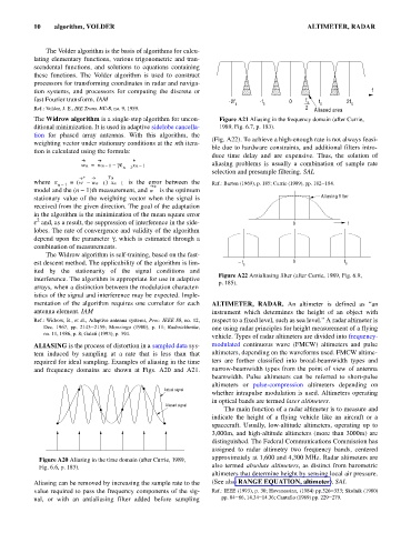
(Fig. A22). To achieve a high-enough rate is not always feasi-
weighting vector under stationary conditions at the nth itera-
ble due to hardware constraints, and additional filters intro-
tion is calculated using the formula:
duce time delay and are expensive. Thus, the solution of
wn = wn – – ge xn – 1 aliasing problems is usually a combination of sample rate
1
n 1–
selection and presample filtering. SAL
* T
where e = ( w – wn – 1 ) xn – 1 is the error between the Ref.: Barton (1969), p. 185; Currie (1989), pp. 182–184.
n – 1 *
model and the (n - 1)th measurement, and w is the optimum
stationary value of the weighting vector when the signal is Aliasing filter
received from the given direction. The goal of the adaptation
in the algorithm is the minimization of the mean square error
2
e and, as a result, the suppression of interference in the side- 0 f
lobes. The rate of convergence and validity of the algorithm
depend upon the parameter g, which is estimated through a
combination of measurements.
The Widrow algorithm is self-training, based on the fast-
est descent method. The applicability of the algorithm is lim- f s 0 f s
ited by the stationarity of the signal conditions and
Figure A22 Antialiasing filter (after Currie, 1989, Fig. 6.9,
interference. The algorithm is appropriate for use in adaptive
p. 185).
arrays, when a distinction between the modulation character-
istics of the signal and interference may be expected. Imple-
mentation of the algorithm requires one correlator for each ALTIMETER, RADAR. An altimeter is defined as “an
antenna element. IAM instrument which determines the height of an object with
Ref.: Widrow, B., et al., Adaptive antenna systems, Proc. IEEE 55, no. 12, respect to a fixed level, such as sea level.” A radar altimeter is
Dec. 1967, pp. 2143–2159; Monzingo (1980), p. 11; Radiotekhnika, one using radar principles for height measurement of a flying
no. 11, 1986, p. 8; Galati (1993), p. 394.
vehicle. Types of radar altimeters are divided into frequency-
ALIASING is the process of distortion in a sampled data sys- modulated continuous wave (FMCW) altimeters and pulse
tem induced by sampling at a rate that is less than that altimeters, depending on the waveforms used. FMCW altime-
required for ideal sampling. Examples of aliasing in the time ters are further classified into broad-beamwidth types and
and frequency domains are shown at Figs. A20 and A21. narrow-beamwidth types from the point of view of antenna
beamwidth. Pulse altimeters can be referred to short-pulse
altimeters or pulse-compression altimeters depending on
Actual signal
whether intrapulse modulation is used. Altimeters operating
in optical bands are termed laser altimeters.
Aliased signal
The main function of a radar altimeter is to measure and
indicate the height of a flying vehicle like an aircraft or a
spacecraft. Usually, low-altitude altimeters, operating up to
3,000m, and high-altitude altimeters (more than 3000m) are
distinguished. The Federal Communications Commission has
assigned to radar altimetry two frequency bands, centered
approximately at 1,600 and 4,300 MHz. Radar altimeters are
Figure A20 Aliasing in the time domain (after Currie, 1989,
Fig. 6.6, p. 183). also termed absolute altimeters, as distinct from barometric
altimeters that determine height by sensing local air pressure.
Aliasing can be removed by increasing the sample rate to the (See also RANGE EQUATION, altimeter). SAL
value required to pass the frequency components of the sig- Ref.: IEEE (1993), p. 30; Hovanessian, (1984) pp.326–333; Skolnik (1980)
nal, or with an antialiasing filter added before sampling pp. 84–86, 14.34–14.36; Cantafio (1989) pp. 229–279.