
Page 25 - Radar Technology Encyclopedia
P. 25
ambiguity function, ideal amplifier, aperiodic 15
The ideal ambiguity function is that of the waveform with 2
c
1 | (t , f )|
d
d
ideal resolution of targets no matter how close they are B
located. It consists of a single peak of infinitesimal thickness 1
at the origin and is equal to zero everywhere else (Fig. A32). T 1
f
The ideal ambiguity function is an idealized notion, and can d BT
never be achieved in practice because of the fundamental
properties of the ambiguity function. SAL
Ref.: Skolnik (1980), p. 412.
t
d
c
| (t , f )| 2 2 B
d
d
f 2 T
d
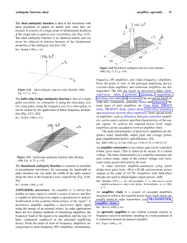
Figure A34 Thumbtack ambiguity function (after Skolnik,
1980, Fig. 11.13, p. 419).
t frequency (IF) amplifiers, and video(-frequency) amplifiers.
d
From the point of view of the principal amplifying device,
(vacuum-)tube amplifiers and solid-state amplifiers are dis-
Figure A32 Ideal ambiguity function (after Skolnik, 1980, tinguished. The first are based on microwave tubes: back-
Fig. 11.7, p. 413).
ward-wave tubes, gyrotrons, klystrons, magnetrons,
The knife-edge [ridge] ambiguity function is that of a single traveling-wave tubes, and twystrons. The second are based on
pulse waveform. Its orientation is along the time-delay axis solid-state components, primarily diodes and transistors. The
for a long pulse, along the frequency axis for a short pulse, or main types of such amplifiers are Gunn diode, IMPATT
can be rotated by the application of linear frequency modula- diode, TRAPATT diode, tunnel diode, field-effect transistor,
tion (Fig. A33). SAL and transferred electron effect amplifiers. Some special kinds
of amplifiers, such as difference and gain-controlled amplifi-
Ref.: Skolnik (1980) p. 418.
ers, can be used to achieve specified characteristics of the out-
c (t , f ) 2 put signals. To achieve the required power level, single
d
d
f d amplifiers can be cascaded to form an amplifier chain.
The main characteristics of microwave amplifiers are fre-
quency band, bandwidth, output peak and average power,
gain (amplification factor), and efficiency. SAL
Ref.: IEEE (1993), p. 32; Fink (1982), pp. 13.60–13.70, 13.100–13.117.
t d An amplifier-attenuator is one whose gain can be controlled
within given limits. This is achieved by means of a control
voltage. The basic characteristics of a amplifier-attenuator are
Figure A33 Knife-edge ambiguity function (after Skolnik,
gain control range, range of the control voltage, and maxi-
1980, Fig. 11.13, p. 419).
mum output power delivered to the load.
The thumbtack ambiguity function is common to noiselike In radar receivers amplifier-attenuators using tunnel
or pseudonoise waveforms. By increasing the bandwidth or diodes have gains from -30 to +20 dB, and maximum power
- 5
pulse duration one can make the width of the spike narrow outputs of the order of 10 W. Amplifiers with field-effect
along the time or the frequency axis, respectively (Fig. A34). tetrodes are used to obtain higher output powers. IAM
SAL Ref.: Rudenko (1971), p. 92.; Musiyachenko, V. A., Microwave control
Ref.: Skolnik (1980), p. 418. amplifier-attenuators using tunnel diodes, Radiotekhnika, no. 6, 1986,
p. 31.
AMPLIFIER, microwave. An amplifier is “a device that
An amplifier chain is a system of cascaded amplifiers
enables an input signal to control a source of power, and thus
designed to achieve the required power level. Such chains are
is capable of delivering at its output a reproduction or analytic
usually found in radar transmitters (see TRANSMITTER,
modification of the essential characteristics of the signal.” A
amplifier chain).
microwave amplifier amplifies a microwave input signal
Ref.: Skolnik (1990), p. 4.9.
using the energy of an external source. In radar applications
there are two primary methods of classifying amplifiers: the An aperiodic amplifier is one without resonant circuits or
frequency band of the signal to be amplified, and the type of frequency-selective elements, resulting in a wide passband. It
basic component employed as the principal amplifying is sometimes termed an untuned amplifier.
device. From the point of view of frequency, amplifiers are Ref.: Popov (1980), p. 40.
categorized as radio-frequency (RF) amplifiers, intermediate-