
Page 28 - Radar Technology Encyclopedia
P. 28
18 amplifier, intermediate-frequency (IF) amplifier, master-oscillator power (MOPA)
The basic amplifier parameters are intermediate fre- Table A3
quency, gain, passband width, passband shape, and selectiv- Noise Performance of Amplifiers
ity. The passband shape defines the frequency response levels
relative to the maximum gain in the passband. The selective Low-Noise Amplifier Component Noise Temperature (K)
properties of the amplifier are determined by the choice of the
Tunnel diode 200 – 800
frequency-selective filters. At the customary frequencies of
IF amplifiers, 10 to 120 GHz, these are L-C filters, quartz Bipolar transistor 100 – 700
crystals, solid-state piezoelectric, and supersonic surface
wave filters. SAL, IAM Field-effect transistor 70 – 100
Ref.: Sokolov (1984), p. 249; Popov (1980), p. 448; Leonov (1988), p. 63;
Skolnik (1990), pp. 3.17–3.32. Parametric (uncooled) 30 – 50
A klystron amplifier is one intended for the amplification of Field-effect transistor (cooled) 13 – 30
energy at microwave frequencies. For amplifier applications,
a klystron with multiple resonators and having one or several Parametric (cooled) 10 – 20
electron beams is generally used. The klystron amplifier gain
ranges from 30 to 70 dB, bandwidth 1 to 8%, efficiency up to Quantum parametric (cooled) 4 – 5
30%. Output circuit resonators with extended distributed
interaction regions provide bandwidths of 10 to 15% with A magnetron amplifier is one based on a crossed-field device.
efficiencies of up to 65%. Klystrons are used in radars to It represents a microwave device wherein the amplification of
achieve high microwave output power levels. Power an electromagnetic wave, propagating in a slow-wave struc-
klystrons have peak power levels exceeding 10 MW (see also ture, is realized by an extended interaction with the electronic
KLYSTRON). IAM beam moving within crossed electric and magnetic fields.
Ref.: Chaikov (1974), p. 5.; Skolnik (1990), p. 4.14. Magnetron amplifier types are built using either linear or cir-
A lin(ear)-log(arithmic) amplifier is an automatic gain con- cular (annular) electrodes (Figs. A35, A36). Most magnetron
trol amplifier that operates in a linear manner for low-ampli- amplifiers use the circular geometry, which allows reduction
tude input signals and in a logarithmic manner for high- of the overall dimensions of the device and simplifies the
amplitude input signals. SAL construction of the magnetic circuit. Magnetron amplifiers
operate both in CW and pulse modes. The range of operating
Ref.: Johnston (1979), p. 62.
frequencies generally extends from 0.4 to 17 GHz, with gains
A log(arithmic) amplifier is one whose output voltage is
to 20 dB, and peak power outputs up to 10 MW (see also
proportional to the logarithm of its input voltage. The loga-
CROSSED-FIELD AMPLIFIER). IAM
rithmic amplitude characteristic is typically obtained by
Ref.: Fink (1982), p. 13.117; Leonov (1988), p. 49.
shunting the loads of amplifier stages, by nonlinear circuits,
or by successive summing of the output voltages of several
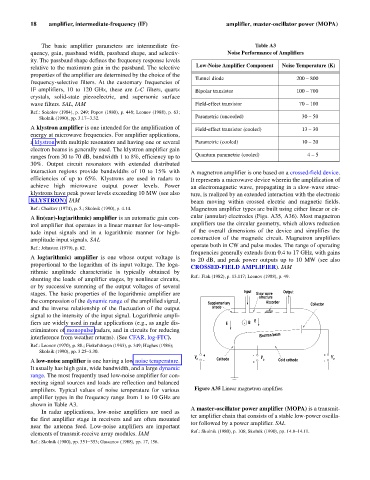
Input Output
stages. The basic properties of the logarithmic amplifier are Slow wave
structure
the compression of the dynamic range of the amplified signal, Supplementary Absorber Collector
and the inverse relationship of the fluctuation of the output anode
signal to the intensity of the input signal. Logarithmic ampli-
fiers are widely used in radar applications (e.g., as angle dis- E + B E
criminators of monopulse radars, and in circuits for reducing
interference from weather returns). (See CFAR, log-FTC). Electron beam
Ref.: Leonov (1970), p. 88.; Finkel'shteyn (1983), p. 349; Hughes (1986);
Skolnik (1990), pp. 3.25–3.30.
+ - +
V a Cathode V Cold cathode V o
A low-noise amplifier is one having a low noise temperature. - + k -
It usually has high gain, wide bandwidth, and a large dynamic
range. The most frequently used low-noise amplifier for con-
necting signal sources and loads are reflection and balanced
amplifiers. Typical values of noise temperature for various Figure A35 Linear magnetron amplifier.
amplifier types in the frequency range from 1 to 10 GHz are
shown in Table A3.
A master-oscillator power amplifier (MOPA) is a transmit-
In radar applications, low-noise amplifiers are used as
ter amplifier chain that consists of a stable low-power oscilla-
the first amplifier stage in receivers and are often mounted
tor followed by a power amplifier. SAL
near the antenna feed. Low-noise amplifiers are important
Ref.: Skolnik (1980), p. 106; Skolnik (1990), pp. 14.8–14.11.
elements of transmit-receive array modules. IAM
Ref.: Skolnik (1980), pp. 351–353; Gassanov (1988), pp. 17, 156.