
Page 27 - Radar Technology Encyclopedia
P. 27
amplifier, doppler and range frequencies amplifier, intermediate-frequency (IF) 17
the target return and the effects related to wave propagation, parameter at the input (I , V , P ). The gain, G, is unambiguous
i
i
i
automatic gain control is used. IAM when expressed in decibels:
Ref.: Vinitskiy (1961), p. 267.
I o V o P o
G = 20log ---- = 20log ------ = 10log ------
Amplifier efficiency is the ratio of the power P delivered to dB I i V i P i
o
the output load to the power P accepted from the amplifier
s
power source: When the amplifier and its load contain reactances, amplifier
gain is frequency-dependent. Typically amplifier gain is
P
h = /P s
o
stated for the middle frequencies in the specified band, where
Ref.: IEEE (1993), p. 407.
it is not sensitive to the frequency. Gain is often called avail-
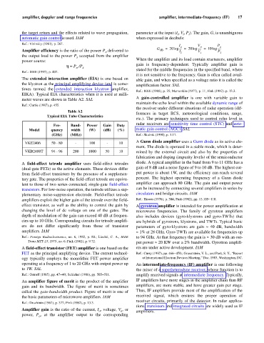
The extended interaction amplifier (EIA) is one based on able gain, and when specified as a voltage ratio it is called the
the klystron as the principal amplifying device (and is some- amplification factor. SAL
times termed the extended interaction klystron amplifier,
Ref.: IEEE (1988), p. 35; Mamonkin (1977), p. 11; Fink (1982). p. 13.3.
EIKA). Typical EIA characteristics when it is used at milli-
A gain-controlled amplifier is one with variable gain to
meter waves are shown in Table A2. SAL
maintain the echo level within the available dynamic range of
Ref.: Currie (1987), p. 455.
the receiver under different situations of radar operation (dif-
Table A2
ferences in target RCS, meteorological conditions, range,
Typical EIA Tube Characteristics
etc.). The primary techniques used to control echo level in
radar receivers are sensitivity time control (STC) and auto-
Fre- Band- Power Gain Duty
Model quency width (W) (dB) (%) matic gain control (AGC). SAL
(GHz) (MHz) Ref.: Skolnik (1990), p. 3.17.
A Gunn diode amplifier uses a Gunn diode as its active ele-
VKE2406 50 - 80 - 100 - 10
ment. The diode is operated in a stable mode, which is deter-
VKB2400T 94 - 96 200 1000 30 10 mined by the external circuit and also by the properties of
fabrication and doping (impurity levels) of the semiconductor
A field-effect tetrode amplifier uses field-effect tetrodes diode. A typical amplifier in the band from 9 to 11 GHz has a
(dual-gate FETs) as the active elements. These devices differ gain of 8 dB and a noise figure of 9 to 10 dB. The highest out-
from field-effect transistors by the presence of a supplemen- put power is about 1W, and the efficiency can reach several
tary gate. The properties of the field-effect tetrode are equiva- percent. The highest operating frequency of a Gunn diode
lent to those of two series-connected, single-gate field-effect amplifier can approach 80 GHz. The gain and output power
transistors. For low-noise operation, the tetrode utilizes a sup- can be increased by connecting several amplifiers in series by
plementary noise-suppression electrode. Field-effect tetrode circulators and bridge circuits. IAM
amplifiers exploit the higher gain of the tetrode over the field- Ref.: Howes (1976), p. 304; Fink (1982), pp. 13.105–110.
effect transistor, as well as the ability to control the gain by A gyrotron amplifier is intended for power amplification at
changing the level of dc voltage on one of the gates. The microwave frequencies. The family of gyrotron amplifiers
depth of modulation of the gain can exceed 40 dB at frequen- also includes devices (gyro-klystrons and gyro-TWTs) that
cies up to 10 GHz. Corresponding circuits for tetrode amplifi- are hybrids of gyrotrons, klystrons, and TWTs. Typical basic
ers do not differ significantly from those of transistor parameters of gyro-klystrons are gain » 40 dB, bandwidth
amplifiers. IAM »1% at 28 GHz. Gyro-TWTs are available for frequencies up
Ref.: Foreign Radioelectronics, no. 6, 1982, p. 80.; Liechti, C. A., IEEE to 94 GHz. At that frequency the gain is » 30 dB with an out-
Trans MTT-23, 1975, no. 6; Fink (1982), p. 9.72. put power » 20 KW over a 2% bandwidth. Gyrotron amplifi-
A field-effect transistor (FET) amplifier is one based on the ers are under active development. IAM
FET as the principal amplifying device. The current technol- Ref.: Curry (1987), pp. 466–470.; Granatstein, V. L., and Park, S. Y., “Report
ogy typically employs the monolithic FET power amplifier at International Electron Devices Meeting,” Dec. 1983, Washington, DC.
operating at a frequency of 1 to 20 GHz with output power up An intermediate-frequency (IF) amplifier is one following
to 1W. SAL the mixer of a superheterodyne receiver, whose function is to
Ref.: Ostroff (1985), pp. 47–49; Schleher (1986), pp. 505–511. amplify received signals at intermediate frequency. Typically,
An amplifier figure of merit is the product of the amplifier IF amplifiers have more stages in the amplifier chain than RF
gain and its bandwidth. The figure of merit is sometimes amplifiers, are more stable, and have greater gain per stage.
called the gain-bandwidth product. Figure of merit is one of Thus, IF amplifiers provide most of the amplification of the
the basic parameters of microwave amplifiers. IAM received signal, which ensures the proper operation of
receiver circuits, primarily of the detector. In radar applica-
Ref.: Druzhinin (1967), p. 377; Fink (1982), p. 13.3.
tions, transistors and integrated circuits are widely used as IF
Amplifier gain is the ratio of the current, I , voltage, V , or amplifiers.
o
o
power, P , at the amplifier output to the corresponding
o