
Page 30 - Radar Technology Encyclopedia
P. 30
20 amplifier, pulse amplifier, summing
A pulse amplifier is intended for the amplification of pulse A resistive amplifier is a transistor or vacuum tube amplifier
waveforms. One distinguishes between linear and nonlinear where the load circuit, to obtain the output signal, uses an
amplifiers. Linear amplifiers reproduce the form of the pulse active resistance. It is characterized mainly by a flat amplifi-
with a given accuracy. Nonlinear amplifiers intentionally pro- cation across a wide bandwidth, reaching several megahertz.
duce a distortion of the pulse by changing the amplitude and/ Resistive amplifiers are simple in construction and are used
or duration of the pulse. To compensate for undesired pulse as the components of pulse amplifiers. IAM
distortion, a flat frequency response of the gain over the low, Ref.: Popov (1980), p. 369.
middle, and high frequencies is achieved by feedback and
A resonant amplifier is one using resonant circuits. An
compensation circuits. The most important parameter of the
example of the resonant amplifier is the bandpass amplifier.
linear pulse amplifier, the level of amplifier distortion, is
Among the basic characteristics of the resonant amplifier are
determined by the amplifier transfer function. IAM
the resonant amplification factor (gain at the resonant fre-
Ref.: Agakhanyan (1970), pp.13–15.
quency), selectivity, noise figure, signal distortion levels, and
push-pull amplifier (see balanced amplifier). stability. It is employed as an amplifier at radio frequencies
(RF) and intermediate frequencies (IF). Sometimes this type
A (quantum) paramagnetic amplifier is a microwave
of amplifier is termed the tuned amplifier. IAM
amplifier that uses the energy transfer from excited ions of the
Ref.: Fink (1982), pp. 3.35, 13.3; Buda (1986), p. 59.
active element (paramagnetic substance) to electromagnetic
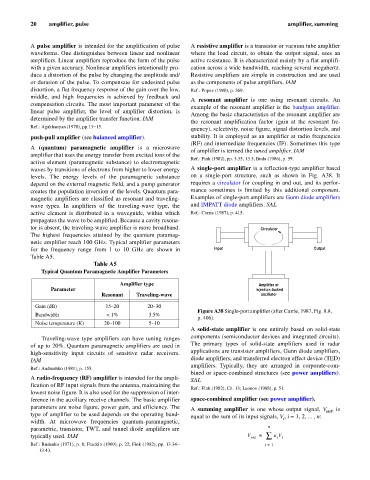
waves by transitions of electrons from higher to lower energy A single-port amplifier is a reflection-type amplifier based
levels. The energy levels of the paramagnetic substance on a single-port structure, such as shown in Fig. A38. It
depend on the external magnetic field, and a pump generator requires a circulator for coupling in and out, and its perfor-
creates the population inversion of the levels. Quantum para- mance sometimes is limited by this additional component.
magnetic amplifiers are classified as resonant and traveling- Examples of single-port amplifiers are Gunn diode amplifiers
wave types. In amplifiers of the traveling-wave type, the and IMPATT diode amplifiers. SAL
active element is distributed in a waveguide, within which Ref.: Currie (1987), p. 415.
propagates the wave to be amplified. Because a cavity resona-
tor is absent, the traveling-wave amplifier is more broadband. Circulator
The highest frequencies attained by the quantum paramag-
netic amplifier reach 100 GHz. Typical amplifier parameters
for the frequency range from 1 to 10 GHz are shown in Input Output
Table A5.
Table A5
Typical Quantum Paramagnetic Amplifier Parameters
Amplifier type Amplifier or
Parameter injection-locked
Resonant Traveling-wave oscillator
Gain (dB) 15–20 20–30
Figure A38 Single-port amplifier (after Currie, 1987, Fig. 8.8,
Bandwidth < 1% 3.5%
p. 406).
Noise temperature (K) 20–100 5–10
A solid-state amplifier is one entirely based on solid-state
Traveling-wave type amplifiers can have tuning ranges components (semiconductor devices and integrated circuits).
of up to 20%. Quantum paramagnetic amplifiers are used in The primary types of solid-state amplifiers used in radar
high-sensitivity input circuits of sensitive radar receivers. applications are transistor amplifiers, Gunn diode amplifiers,
IAM diode amplifiers, and transferred electron effect device (TED)
amplifiers. Typically, they are arranged in corporate-com-
Ref.: Andrushko (1981), p. 155.
bined or space-combined structures (see power amplifiers).
A radio-frequency (RF) amplifier is intended for the ampli- SAL
fication of RF input signals from the antenna, maintaining the
Ref.: Fink (1982), Ch. 13; Leonov (1988), p. 51.
lowest noise figure. It is also used for the suppression of inter-
ference in the auxiliary receive channels. The basic amplifier space-combined amplifier (see power amplifier).
parameters are noise figure, power gain, and efficiency. The A summing amplifier is one whose output signal, V , is
out
type of amplifier to be used depends on the operating band- equal to the sum of its input signals, V , i = 1, 2, ... , n:
i
width. At microwave frequencies quantum-paramagnetic,
n
parametric, transistor, TWT, and tunnel diode amplifiers are
typically used. IAM V out = å a V
i i
Ref.: Rudenko (1971), p. 8; Fradkin (1969), p. 22; Fink (1982), pp. 13.34– i = 1
13.43.