
Page 29 - Radar Technology Encyclopedia
P. 29
amplifier, negative resistance amplifier, power 19
amplifiers. The active elements in power amplifiers can be
Slow wave Absorber
structure either vacuum tubes or semiconductor devices. Table A4
shows typical values of output power levels, in watts, for dif-
Cold
cathode ferent types of power amplifiers.
E Table A4
+
B Range of Amplifier Output Powers (W)
Operating frequency (GHz)
Type of power
amplifier
1.0 10 100
Cathode
Vacuum tubes:
Input Output 5 4
Klystron 5´ 10 10
Collector 4 3 2
Supplementary TWT 3´ 10 3´ 10 10
anode
Semiconductors:
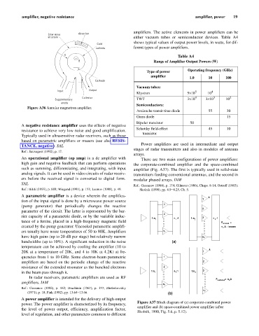
Figure A36 Annular magnetron amplifier.
Avalanche transit time diode 55 30
Gunn diode 15
Bipolar transistor 50
A negative resistance amplifier uses the effects of negative
Schottky field-effect 45 10
resistance to achieve very low noise and good amplification.
transistor
Typically used in ultrasensitive radar receivers, such as those
based on parametric amplifiers or masers (see also RESIS-
Power amplifiers are used in intermediate and output
TANCE, negative). SAL
stages of radar transmitters and also in modules of antenna
Ref.: Sauvageot (1992), p. 17.
arrays.
An operational amplifier (op amp) is a dc amplifier with There are two main configurations of power amplifiers:
high gain and negative feedback that can perform operations the corporate-combined amplifier and the space-combined
such as summing, differentiating, and integrating, with input amplifier (Fig. A37). The first is typically used in solid-state
analog signals. It can be used in video circuits of radar receiv- transmitters feeding conventional antennas, and the second in
ers before the received signal is converted to digital form. modular phased arrays. IAM
SAL
Ref.: Gassanov (1988), p. 174; Gilmour (1986), Chaps. 8-14; Ostroff (1985);
Ref.: IEEE (1993), p. 889; Wiegand (1991), p. 151; Leonov (1988), p. 49. Skolnik (1990), pp. 4.9–4.25, Ch. 5.
A parametric amplifier is a device wherein the amplifica- A
1
tion of the input signal is done by a microwave power source
(pump generator) that periodically changes the reactive 1
2
parameter of the circuit. The latter is represented by the bar-
2
rier capacity of a parametric diode, or by the variable induc-
1:n 1 n :1 1:n 2 3 n :1
1
2
tance of a ferrite, placed in a high-frequency magnetic field P radiated =
created by the pump generator. Uncooled parametric amplifi- n A - losses
2
ers usually have noise temperatures of 50 to 80K. Amplifiers n 1
have high gains (up to 20 dB per stage) but relatively narrow n 2
bandwidths (up to 10%). A significant reduction in the noise (a)
temperature can be achieved by cooling the amplifier (10 to
A
20K at a temperature of 20K, and 4 to 10K at 4.2K) at fre- 1
quencies from 1 to 10 GHz. Some electron-beam parametric 1
amplifiers are based on the periodic change of the reactive 2
resistance of the extended resonator as the bunched electrons 2
in the beam pass through it. 1:n 1 n :1 1:n 2 3
1
In radar receivers, parametric amplifiers are used as RF
P radiated = n A
2
amplifiers. IAM
n 1
Ref.: Gassanov (1988), p. 162; Druzhinin (1967), p. 357; Zhelerkovskiy
n 2
(1971), p. 10; Fink (1982), pp. 13.64–13.66. (b)
A power amplifier is intended for the delivery of high output
Figure A37 Block diagram of (a) corporate-combined power
power. The power amplifier is characterized by its frequency,
amplifier and (b) space-combined power amplifier (after
the level of power output, efficiency, amplification factor,
Skolnik, 1990, Fig. 5.6, p. 5.12).
level of regulation, and other parameters common to different