
Page 33 - Radar Technology Encyclopedia
P. 33
ANECHOIC CHAMBER angle, Brewster 23
The main characteristic of the chamber is an anechoic
North
coefficient, which is defined as the ratio of spurious scattered
power density at the specified point to the transmitted power
density. The value of the anechoic coefficient is determined
by the quality of the radar-absorbing material, the shape of Azimuth
angle
the chamber, and the place of measurement. The admissible
value of the anechoic coefficient is defined by the antenna
sidelobe levels and the required measurement accuracy. Typi-
cally, this value is about -40 to -60 dB. East
The basic underlying data to design the measurement
section of anechoic chamber is the frequency band, assumed
characteristics of the objects to be tested and their dimen-
sions, absorbing materials performance, and cost constraints. Figure A41 Azimuth angle, measured from north.
Typically, anechoic chambers are used to measure antenna
performance and for RCS measurements. Recently, radar Bearing angle is “the angle in the horizontal plane between a
holography methods came into use to measure fine structure reference line and the horizontal projection of the line joining
of radar target backscattering. PCH, IAM two points.” It is usually expressed in degrees measured
Ref.: Mayzel’s (1972), p. 109; Strakhov (1985), p. 102; Tuchkov (1985), clockwise form the reference. Relative bearing is to some
p. 149; Van Nostrand (1983), p.154; Fink (1982), p. 6.28.
arbitrary reference: absolute bearing is to North. AIL
ANGEL (ECHO). An angel echo is “a radar echo caused by Ref.: Popov (1980), p. 280; IEEE (1993), p. 102; ITT (1975), p. 32.8.
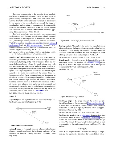
meteorological conditions, such as clouds, atmospheric inho- Bistatic angle is the angle between the lines of sight from the
mogeneities, lightning, or by birds or insects.” There are two transmitter and to the receiver of a bistatic radar system
general classes of angel echoes: dot angels arising from birds (Fig. A42). When the angle approaches 180° the system
,
and insects that are point targets, and distributed angels aris- operates in the forward-scattering mode. DKB
ing from inhomogeneities of the refractive index of the atmo-
Ref.: Willis (1991), p. 2.
sphere. The degrading effects of dot and distributed angels
depend on the radar cross section of the source. Birds and Radar
transmitter
insects, especially in large concentrations, can also appear as
distributed targets and have a degrading effect on radar opera-
tion. Other primary angel sources are clear-air turbulence,
Bistatic
boundary surfaces between differentially moistened surface angle
air masses over adjacent cold and warm water, mineral and
organic particles carried into the air by heavy winds and thun-
derstorms, smoke particles and debris caused by forest and
dump fires, and so forth (see also CLUTTER). SAL
Ref.: IEEE (1993), p. 38; Skolnik (1980), pp. 508–512. Radar
receiver
ANGLE Figure A42 Bistatic angle defined.
Aspect angle is the angle between the radar line of sight and
The Bragg angle is the angle between the normal and dif-
the longitudinal axis of a target (Fig. A40).
fracted laser beam in the acousto-optic Bragg-cell receiver, or
between the mean sea surface and the direction of enhanced
Target backscatter caused by a regular pattern of waves or ripples.
axis The usual notation is a . SAL
Aspect B
angle Ref.: Long (1983), p. 81; Neri (1991), p. 297; Zmuda (1994), p. 417
The Brewster angle is the grazing angle from the interface
between two media at which the reflection coefficient of light
is zero. For radar waves, the reflection coefficient may not go
to zero. The pseudo-Brewster angle is then defined as that
Radar
corresponding to the minimum reflection coefficient, G, of the
Figure A40 Aspect angle defined.
surface:
Azimuth angle is “the angle between a horizontal reference G = r exp(jf)
direction (usually north) and the horizontal projection of the where r, the magnitude of G, describes the change in ampli-
direction of interest, usually measured clockwise” (see tude and the argument f describes the phase shift on reflec-
Fig. A41).