
Page 32 - Radar Technology Encyclopedia
P. 32
22 amplifier, video(-frequency) ANECHOIC CHAMBER
the amplitude of the pulses. The main features of a video mining characteristics of an intercepted radar waveform,
amplifier are broadbandness, large dynamic range, and effi- including its carrier frequency and modulations imposed
ciency. IAM thereon. IAM
Ref.: VanVoorhis (1948), pp. 515–544; Fradkin (1969), p. 62. Ref.: Vasin (1977), p. 26; Wiley (1993), pp. 199–236.
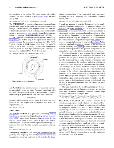
The AMPLITRON is a reentrant beam, continuous cathode, A spectrum analyzer is a device that determines the ampli-
crossed-field amplifier in which the electron current moves tude of the frequency components in a spectrum. A basic ana-
through crossed electric and magnetic fields and interacts lyzer is a harmonic resonator, which may be an electrical
with a back harmonic wave. It is distinguished by the combi- resonator or a bandpass filter with constant parameters, a
nation of an open slow-wave circuit with an electron current piezoelectric or other electromechanical resonator, or other
closed in a ring (see CROSSED-FIELD AMPLIFIER). similar device. Depending on its principle of operation, a
An amplitron is similar in construction to a multicavity spectrum analyzer may be categorized as a simultaneous
magnetron, and differs only in the open-circuit multicavity (full-band) analyzer, a sequential analyzer with a tuned reso-
anode block and the existence of an input port (Fig. A39). nator, or a sequential analyzer with a tuned oscillator. When
Typical gain is 6 to 15 dB, bandwidth is 8 to 15%, and effi- analyzing wideband signals, it is common to use a sequential
ciency is 40 to 80%. Physically, it looks like a magnetron analyzer consisting of a mixer, oscillator, resonator, and an
oscillator, but it has both input and output ports. This type of indicator. Various portions of the spectrum being analyzed are
tube was invented in 1953 by W. C. Brown. SAL successively presented within the passband of the resonator.
Ref.: Brookner (1988), p. 263; Zherebtsov (1989), p. 342. If an optical device is used to determine the amplitude
(and sometimes phase) of the frequency components of a
Anode block spectrum, the analyzer is termed an optical spectrum ana-
Cathode
lyzer. Its operation is based on the property of an optical lens
by which it transforms the amplitude and phase distribution
of an optical signal into a spatial spectrum in the focal plane.
One advantage of an optical spectrum analyzer is that the
incident signal is processed in real time. The fundamental
B
+
parameter of the analyzer – its resolution – depends upon the
frequency of the signal and the characteristics of the optical
Input line
system. Optical spectrum analyzers are employed in radars
using optical signal processing. In such a system the radio fre-
Output line quency signal is first transformed into an optical signal with
Figure A39 Amplitron amplifier.
the help of an optical modulator, which is usually an ultra-
sonic delay line.
The main parameters of a spectrum analyzer are its reso-
AMPLITUDE is the maximum value of a quantity that var-
lution and analysis period. Spectrum analyzers are used in
ies periodically or as any other function. “Amplitude of a
radars with continuous frequency modulation to obtain range
sinusoidal electromagnetic wave is the maximum value of a
coverage of an observation region. IAM
field quantity in space or time.” For the simple sine wave:
Ref.: Supryaga (1974), p. 51; Vinitskiy (1961), p. 318; Scheer (1993), pp.
(
Asin wt + q ) 346–367; Finkel’shteyn (1983), p. 459; Zmuda (1994), pp. 435–442.
the amplitude is positive real A, where A, w, and q are con- ANECHOIC CHAMBER. An anechoic chamber is a
stants. In this case, amplitude is synonymous with maximum closed, screened premise inside which the conditions of free-
or peak value. SAL space propagation are simulated by using special methods
Ref.: IEEE (1993), p. 34 and equipment. Literally, it is a room “without echoes.” For
radar testing, an anechoic chamber is a room lined with a
ANALYZER
material designed to absorb RF energy without reflection so
The Fourier analyzer is a processor performing Fourier that transmitted and received signal measurements will accu-
transforms in analog form. Typically, chirp surface-acoustic- rately represent the true characteristics of the unit under test
wave (SAW) transmission lines and charge-coupled devices without interference from spurious sources. Most anechoic
(CCDs) can be used. In many cases a digital fast Fourier chambers designed for radar testing are lined with broadband
transform (FFT) technique is more expedient in radar applica- geometric transition absorbers, which are wedges or pyrami-
tions, as it is more flexible and provides greater accuracy. dal shapes of carbon-loaded synthetic sponge rubber.
SAL Typically, anechoic chambers have rectangular or horn-
Ref.: Brookner (1977), pp. 186, 315. type shapes with the dimensions from few meters to tens of
A frequency analyzer is (1) a device for determining the tar- meters. Usually there are two sections: a room for equipment
get range in a frequency-modulated, continuous-wave radar, and a measurement (test) section.
(essentially a spectrum analyzer), or (2) a device for deter-