
Page 35 - Radar Technology Encyclopedia
P. 35
angle, solid ANTENNA 25
s
the radius. By definition, there are 4p teradians of solid
angle in a unit sphere. Figure A46 demonstrates that, except
for small angles (such as the pencil beam of a tracking radar),
the solid angle is not simply the product of the azimuth and
elevation sectors in radians. PCH Phasefront at f = c/l
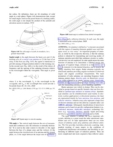
Squint angle 0
q
max
q Phasefront at f = c/l
min
Figure A48 Squint angle in radiation from slotted waveguide.
tion ellipse and a reference direction. In each case, the angle
max
is measured in the vertical plane. DKB
q
min
Ref.: IEEE (1993), p. 1374.
ANTENNA. An antenna is defined as “a structure associated
A m with the region of transition between guided wave and free-
Figure A46 The solid angle of search, in steradians, for a space wave, or vice versa.” An important property of anten-
ground- based radar. nas, as stated by the reciprocity theorem, is that the antenna
pattern is identical for transmitting and receiving modes of
Squint angle is the angle between the beam axis and (1) the
antenna operation provided that nonlinear circuits (or unilat-
tracking axis of a conical scan antenna or (2) the face of an
eral devices) are not employed. In radar applications the main
array. In the first case (Fig. A47), the squint is intentional, to
function of antenna is to concentrate a radiated energy into
provide sensing of target position relative to the tracking axis.
the beam of required shape, referred to as the antenna pat-
In the second case (Fig. A48), it is the result of the choice of
tern, to transmit it in the desired direction, and to receive the
frequency and the spacing of the radiating elements relative
energy returning from targets. Radar antennas typically are
to the wavelength within the waveguide. This angle is given
directional antennas providing angular resolution of observed
by
targets and angular coordinate measurement. The main
1
1
æ
sin q = l ----- -------- ö parameters of radar antennas are operating frequency band,
–
è l l ø
g go antenna pattern shape, directive gain (or directivity), power
gain (often referred to as simply antenna gain), beamwidth,
where l is the wavelength, l is the wavelength in the sidelobe level, polarization type, voltage standing-wave ratio,
g
waveguide, and l is the wavelength that would provide a and (for transmitting antennas) power handling capability.
go
broadside beam (q = 0). SAL, DKB
Radar antennas vary widely in design. They can be clas-
Ref.: IEEE (1993), p. 1,268; Skolnik (1970), pp. 13.2–13.5; (1980), pp. 155, sified in groups based on specific features: they are first clas-
158.
sified as aperture-type antennas or antenna arrays. Aperture-
Beam axis
type antennas can be omnidirectional (used mainly in elec-
Tracking axis tronic warfare applications) or directional antennas; the latter
Squint angle are represented mainly by horn antennas, lens antennas, and
Antenna beam Beam reflector antennas. Antenna arrays also represent a large class
of discrete antennas and are described in a separate entry (see
rotation
ARRAY, antenna). Subsequent classifications of microwave
antennas can be based on specific configuration features (e.g.,
Radar conformal antennas, deployable antennas); technology fea-
tures (e.g. microstrip antenna); specific signal processing
involved (e.g. synthetic aperture antenna); and so forth.
The radar antenna is perhaps the most important sub-
system, defining to a great extent the radar operational capa-
Figure A47 Squint angle in conical scanning.
bilities and cost. In radar applications there are two main
Tilt angle is “the vertical angle between the axis of measure- classes of antennas used: array antennas and reflector anten-
ment and a reference axis; the reference is normally horizon- nas. The first provides inertialess electronic scanning, inde-
tal.” It is used in the radar context to describe (1) the angle pendent tracking of many targets in the conditions of
between the face of a planar array and the vertical, (2) the complicated interference environment, and flexibility in syn-
angle between the electrical axis of an antenna and the ground thesizing of different types of radiation patterns. They are
plane, or (3) the angle between the major axis of a polariza- more complicated and more expensive than reflector anten-