
Page 39 - Radar Technology Encyclopedia
P. 39
antenna, dipole antenna, dummy 29
tance behind the dipoles to obtain unidirectional radiation. high gain and low sidelobes are desired. What is more, there
Dipoles are used in metric and decimetric wave bands. AIL is a practical upper limit to the size of an antenna having a
Ref.: Johnson (1984), p. 4.3; Sazonov (1988), p. 222; Mailloux (1994), pp. Dolph-Chebyshev pattern, and therefore a lower limit to the
240–267. beamwidth. SAL
A directional antenna is one radiating and receiving electro- Ref.: Skolnik (1980), p. 257.
magnetic energy along one or several main directions. Basic antenna drive (see DRIVE, antenna).
directivity characteristics include directive gain, power gain,
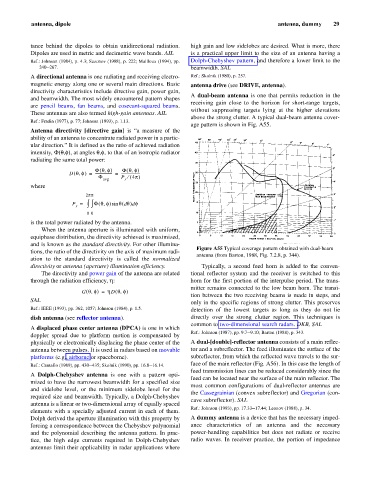
A dual-beam antenna is one that permits reduction in the
and beamwidth. The most widely encountered pattern shapes
receiving gain close to the horizon for short-range targets,
are pencil beams, fan beams, and cosecant-squared beams.
without suppressing targets lying at the higher elevations
These antennas are also termed high-gain antennas. AIL
above the strong clutter. A typical dual-beam antenna cover-
Ref.: Fradin (1977), p. 77; Johnson (1993), p. 1.13.
age pattern is shown in Fig. A55.
Antenna directivity [directive gain] is “a measure of the
ability of an antenna to concentrate radiated power in a partic-
ular direction.” It is defined as the ratio of achieved radiation
intensity, F(q,f) angles q,f,that of an isotropic radiator
at
to
,
radiating the same total power:
(
Fq f) Fq f,( )
,
D qf,( ) ------------------- = ---------------------
=
F P ¤ ( 4p )
avg r
where
2p p
P = ò ò ( , qq ) f
d d
Fq f) sin (
r
0 0
is the total power radiated by the antenna.
When the antenna aperture is illuminated with uniform,
equiphase distribution, the directivity achieved is maximized,
and is known as the standard directivity. For other illumina-
Figure A55 Typical coverage pattern obtained with dual-beam
tions, the ratio of the directivity on the axis of maximum radi-
antenna (from Barton, 1988, Fig. 7.2.8, p. 344).
ation to the standard directivity is called the normalized
directivity or antenna (aperture) illumination efficiency. Typically, a second feed horn is added to the conven-
The directivity and power gain of the antenna are related tional reflector system and the receiver is switched to this
through the radiation efficiency, h: horn for the first portion of the interpulse period. The trans-
mitter remains connected to the low beam horn. The transi-
(
,
G qf,( ) = h D qf)
tion between the two receiving beams is made in steps, and
SAL
only in the specific regions of strong clutter. This preserves
Ref.: IEEE (1993), pp. 362, 1057; Johnson (1984), p. 1.5. detection of the lowest targets as long as they do not lie
dish antenna (see reflector antenna). directly over the strong clutter region. This techniques is
common to two-dimensional search radars. DKB, SAL
A displaced phase center antenna (DPCA) is one in which
Ref.: Johnson (1987), pp. 9.7–9.10; Barton (1988), p. 343.
doppler spread due to platform motion is compensated by
physically or electronically displacing the phase center of the A dual-[double]-reflector antenna consists of a main reflec-
antenna between pulses. It is used in radars based on movable tor and a subreflector. The feed illuminates the surface of the
platforms (e.g., airborne or spaceborne). subreflector, from which the reflected wave travels to the sur-
face of the main reflector (Fig. A56). In this case the length of
Ref.: Cantafio (1989), pp. 430–435; Skolnik (1990), pp. 16.8–16.14.
feed transmission lines can be reduced considerably since the
A Dolph-Chebyshev antenna is one with a pattern opti-
feed can be located near the surface of the main reflector. The
mized to have the narrowest beamwidth for a specified size
most common configurations of dual-reflector antennas are
and sidelobe level, or the minimum sidelobe level for the
the Cassegrainian (convex subreflector) and Gregorian (con-
required size and beamwidth. Typically, a Dolph-Chebyshev
cave subreflector). SAL
antenna is a linear or two-dimensional array of equally spaced
Ref.: Johnson (1993), pp. 17.33–17.44; Leonov (1988), p. 34.
elements with a specially adjusted current in each of them.
Dolph derived the aperture illumination with this property by A dummy antenna is a device that has the necessary imped-
forcing a correspondence between the Chebyshev polynomial ance characteristics of an antenna and the necessary
and the polynomial describing the antenna pattern. In prac- power-handling capabilities but does not radiate or receive
tice, the high edge currents required in Dolph-Chebyshev radio waves. In receiver practice, the portion of impedance
antennas limit their applicability in radar applications where