
Page 41 - Radar Technology Encyclopedia
P. 41
antenna gain antenna, horn 31
G =20logF bandwidth can be increased by 10 to 1 if the helix is wound
dB
SAL on the surface of a cone with spacing between the turns
Ref.: Johnson (1984), p. 1.5; Skolnik (1990), p. 7.2; Barton (1988), p. 166. increased logarithmically with the turn diameter. Beamwidths
up to 90° are typically obtained. Helices have higher gain
A Gregorian (reflector) antenna is a reflector antenna with
than spiral antennas, relatively lower dissipation losses, but
two concave mirrors (Fig. A57). The main mirror is of para-
their structure is larger than spiral antennas. SAL
bolic shape, and subreflector has elliptic shape. One of the
Ref.: Saad (1971), vol, 2, p. 48; Johnson (1984), p. 13.1; Schleher (1986), p.
foci, F , of the subreflector is located at the focus of the main 480.
1
mirror. The phase center of the feed is placed in the second
A high-gain antenna is one with relatively high gain (tens of
decibels) in the main lobe. These are necessarily directional
Paraboloidal
main antennas, which can be of the array or aperture type.
reflector Ref.: Johnson (1993), p. 1.15.
A “honey” antenna is a broad-beam biconical horn antenna
Other focus Ellipsoidal
of ellipsoid, F subreflector that provides an omnidirectional pattern in the azimuth plane.
2
It is formed by a biconical horn. Outputs with amplitudes pro-
portional to the sine or cosine of the signal’s angle-of-arrival
over the 360° azimuth coverage are formed by specially com-
bining four probes at the bottom of the feed. The main range
Plane
Focus of wavefront of application is direction-finding and electronic warfare sys-
paraboloid F
,
1 tems. SAL
Ref.: Johnson (1993), p. 40.2; Schleher (1986), p. 479.
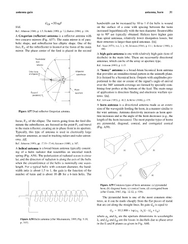
A horn antenna is a directional antenna made as an exten-
sion of the waveguide feeding the horn, in a manner similar to
Figure A57 Dual-reflector Gregorian antenna. the wire antenna. Antenna directivity increases as horn aper-
ture increases and as the angle of the horn decreases (e.g., the
length of the horn increases). The most popular types of horns
focus, F , of the ellipse. The waves going from the feed illu-
2
minate the subreflector, are focused in the point F and travel are pyramidal, diagonal, conical, and corrugated conical
1
to the main reflector, creating an in-phase front in its aperture. (Fig. A59).
Typically, this type of antenna is used in electrically large
reflector antennas, as used in tracking radars and radar astron-
omy. AIL
Ref.: Johnson (1993), pp. 17.33–17.46; Sazonov (1988), p. 387.
A helical antenna is a broad-beam antenna typically consist-
(a) (b)
ing of a helix radiator that resembles an uncoiled watch
spring (Fig. A58). The polarization of radiated waves is circu-
lar, and the direction of radiation is along the axis of the helix
when the circumference of the helix is nominally one wave-
length. For a typical helix with constant diameter, the band-
width ratio is about 1.5 to 1, the gain is the function of the
number of turns and is about 10 dB for a 6-turn helix. The
(c) (d)
Figure A59 Common types of horn antennas: (a) pyramidal
horn; (b) diagonal horn; (c) conical horn; (d) corrugated horn
(after Currie, 1987, Fig. 12.12, p. 539).
The pyramidal horn is one of the most common struc-
tures, as it can be made cheaply from the flat pieces of metal
that are cut along the straight lines. Its gain G is equal to
p
[
G = 10 1.008 + log ( a × b )] L +– ( L )
P l l E H
where a and b are the aperture dimensions in wavelengths
l
l
Figure A58 Helix antenna (after Macnamara, 1995, Fig. 5.18, l , and L and L are the losses in decibels due to phase error
E
H
p. 161).
in the E and H planes as given in Fig. A60.