
Page 43 - Radar Technology Encyclopedia
P. 43
antenna, inflatable antenna, logical synthesis 33
folded up. Inflatable antennas are used in space-based radars.
AIL
Ref.: Gryannik (1987), p. 7; Cantafio (1989), p. 651.
Antenna input impedance defines the ratio of voltage to F
current at transmitting antenna input and characterizes the
antenna as the load for the transmitter. This parameter mainly
is used for linear antennas. AIL
Ref.: Lavrov (1974), p. 28; Blake (1984), p. 159; Johnson (1984), p. 2.11.
inverse Cassegrainian antenna (see Cassegrainian
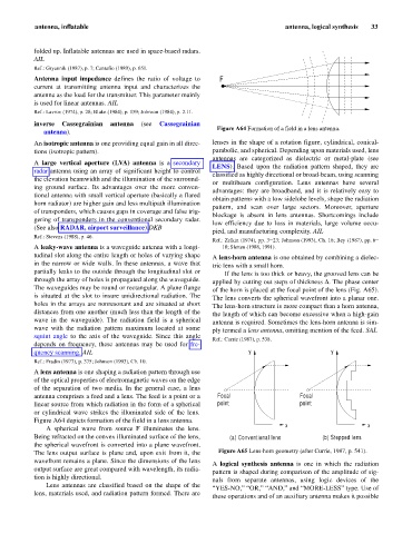
Figure A64 Formation of a field in a lens antenna.
antenna).
An isotropic antenna is one providing equal gain in all direc- lenses in the shape of a rotation figure, cylindrical, conical-
tions (isotropic pattern). parabolic, and spherical. Depending upon materials used, lens
antennas are categorized as dielectric or metal-plate (see
A large vertical aperture (LVA) antenna is a secondary
LENS). Based upon the radiation pattern shaped, they are
radar antenna using an array of significant height to control
classified as highly directional or broad-beam, using scanning
the elevation beamwidth and the illumination of the surround-
or multibeam configuration. Lens antennas have several
ing ground surface. Its advantages over the more conven-
advantages: they are broadband, and it is relatively easy to
tional antenna with small vertical aperture (basically a flared
obtain patterns with a low sidelobe levels, shape the radiation
horn radiator) are higher gain and less multipath illumination
pattern, and scan over large sectors. Moreover, aperture
of transponders, which causes gaps in coverage and false trig-
blockage is absent in lens antennas. Shortcomings include
gering of transponders in the conventional secondary radar.
low efficiency due to loss in materials, large volume occu-
(See also RADAR, airport surveillance).DKB
pied, and manufacturing complexity. AIL
Ref.: Stevens (1988), p. 46.
Ref.: Zelkin (1974), pp. 3–23; Johnson (1993), Ch. 16; Bey (1987), pp. 6–
A leaky-wave antenna is a waveguide antenna with a longi- 10; Sletten (1988, 1991).
tudinal slot along the entire length or holes of varying shape A lens-horn antenna is one obtained by combining a dielec-
in the narrow or wide walls. In these antennas, a wave that tric lens with a small horn.
partially leaks to the outside through the longitudinal slot or If the lens is too thick or heavy, the grooved lens can be
through the array of holes is propagated along the waveguide. applied by cutting out steps of thickness D. The phase center
The waveguides may be round or rectangular. A plane flange of the horn is placed at the focal point of the lens (Fig. A65).
is situated at the slot to insure unidirectional radiation. The The lens converts the spherical wavefront into a planar one.
holes in the arrays are nonresonant and are situated at short The lens-horn structure is more compact than a horn antenna,
distances from one another (much less than the length of the the length of which can become excessive when a high-gain
wave in the waveguide). The radiation field is a spherical antenna is required. Sometimes the lens-horn antenna is sim-
wave with the radiation pattern maximum located at some ply termed a lens antenna, omitting mention of the feed. SAL
squint angle to the axis of the waveguide. Since this angle
Ref.: Currie (1987), p. 538.
depends on frequency, these antennas may be used for fre-
quency scanning. AIL y y
Ref.: Fradin (1977), p. 375; Johnson (1993), Ch. 10.
A lens antenna is one shaping a radiation pattern through use
of the optical properties of electromagnetic waves on the edge
of the separation of two media. In the general case, a lens
antenna comprises a feed and a lens. The feed is a point or a Focal Focal
linear source from which radiation in the form of a spherical point point
or cylindrical wave strikes the illuminated side of the lens.
Figure A64 depicts formation of the field in a lens antenna.
x x
A spherical wave from source F illuminates the lens.
Being refracted on the convex illuminated surface of the lens, (a) Conventional lens (b) Stepped lens
the spherical wavefront is converted into a plane wavefront.
The lens output surface is plane and, upon exit from it, the Figure A65 Lens-horn geometry (after Currie, 1987, p. 541).
wavefront remains a plane. Since the dimensions of the lens
A logical synthesis antenna is one in which the radiation
output surface are great compared with wavelength, its radia-
pattern is shaped during comparison of the amplitude of sig-
tion is highly directional.
nals from separate antennas, using logic devices of the
Lens antennas are classified based on the shape of the
“YES-NO,” “OR,” “AND,” and “MORE-LESS” type. Use of
lens, materials used, and radiation pattern formed. There are
these operations and of an auxiliary antenna makes it possible