
Page 42 - Radar Technology Encyclopedia
P. 42
32 antenna, horn antenna, inflatable
An ideal antenna is a lossless antenna for which the radiation
efficiency is h = 1. In this case the antenna directivity and
gain are identical.
Ref.: Johnson (1993), p. 1.5.
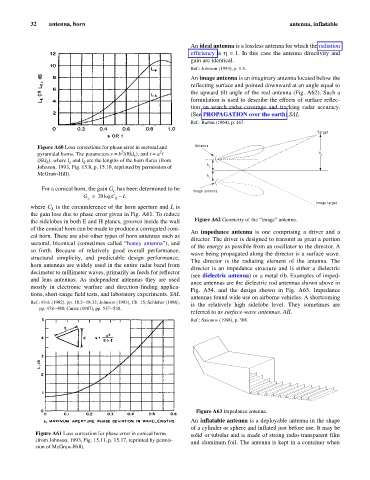
An image antenna is an imaginary antenna located below the
reflecting surface and pointed downward at an angle equal to
the upward tilt angle of the real antenna (Fig. A62). Such a
formulation is used to describe the effects of surface reflec-
tion on search radar coverage and tracking radar accuracy.
(See PROPAGATION over the earth).SAL
Ref.: Barton (1964), p. 167.
Target
Figure A60 Loss corrections for phase error in sectoral and Antenna
2 2
pyramidal horns. The parameters s = b /(8l l ), and t = a / h t
e
(8l l ), where l and l are the lengths of the horn flares (from
h e h
Johnson, 1993, Fig. 15.8, p. 15.10, reprinted by permission of h r
McGraw-Hill). h
r
For a conical horn, the gain G has been determined to be
c Image antenna
G = 20log C – L
l
c
Image target
where C is the circumference of the horn aperture and L is
l
the gain loss due to phase error given in Fig. A61. To reduce
the sidelobes in both E and H planes, grooves inside the wall Figure A62 Geometry of the “image” antenna.
of the conical horn can be made to produce a corrugated coni-
An impedance antenna is one comprising a driver and a
cal horn. There are also other types of horn antennas such as
director. The driver is designed to transmit as great a portion
sectoral, biconical (sometimes called “honey antenna”), and
of the energy as possible from an oscillator to the director. A
so forth. Because of relatively good overall performance,
wave being propagated along the director is a surface wave.
structural simplicity, and predictable design performance,
The director is the radiating element of the antenna. The
horn antennas are widely used in the entire radar band from
director is an impedance structure and is either a dielectric
decimeter to millimeter waves, primarily as feeds for reflector
(see dielectric antenna) or a metal rib. Examples of imped-
and lens antennas. As independent antennas they are used
ance antennas are the dielectric rod antennas shown above in
mostly in electronic warfare and direction-finding applica-
Fig. A54, and the design shown in Fig. A63. Impedance
tions, short-range field tests, and laboratory experiments. SAL
antennas found wide use on airborne vehicles. A shortcoming
Ref.: Fink (1982), pp. 18.2–18.32; Johnson (1993), Ch. 15; Schleher (1986),
is the relatively high sidelobe level. They sometimes are
pp. 478–480; Currie (1987), pp. 537–538.
referred to as surface-wave antennas. AIL
Ref.: Sazonov (1988), p. 308.
Figure A63 Impedance antenna.
An inflatable antenna is a deployable antenna in the shape
of a cylinder or sphere and inflated just before use. It may be
Figure A61 Loss correction for phase error in conical horns solid or tubular and is made of strong radio-transparent film
(from Johnson, 1993, Fig. 15.11, p. 15.17, reprinted by permis-
and aluminum foil. The antenna is kept in a container when
sion of McGraw-Hill).