
Page 44 - Radar Technology Encyclopedia
P. 44
34 antenna, logical synthesis antenna, low-sidelobe
to suppress sidelobes, locking out the main receiving channel Figure A67b depicts an double logarithmic Archimedes
for all signals below a given level. Logical synthesis antennas spiral. The antenna is made of two conductors in a printed
are used to obtain a radiation pattern with a given mainlobe fashion on a thin sheet of high-frequency dielectric. Distance
width and with a low level of sidelobes, which cannot be Dr between conductors and conductor width r re constant
a
achieved using conventional methods. AIL relative to angle. The distance selected between conductors
Ref.: Bakhrakh (1989), p. 15. usually equals the conductor width. A screen is positioned
underneath the spiral for unilateral radiation. However, this
A log-periodic antenna is a broadband antenna with parame-
leads to a reduced bandwidth. AIL
ters which have periodic logarithmic dependence on the oper-
ating frequency. Radiating structures of such antennas may Ref.: Johnson (1993), pp. 14.4–14.32; Sazonov (1988), p. 265; Fradin
(1977), p. 212.
have different shapes. The spatial log-periodic antenna with
an angle y = 90° nsures the radiation in the direction of the lossless antenna (see ideal antenna).
e
apex of the structure (Fig. A66). The direction of the maxi-
A low-noise antenna is one in which special measures are
taken to obtain a low noise temperature. For reflector anten-
nas such measures include: reduction in the illumination at its
(b)
edges; use of supporting feed structures with minimum
(a)
reflecting properties; and use of parabolic reflectors having
small f/D, where f = focal distance; D = parabolic reflector
diameter. However, all these methods reduce noise tempera-
Input
ture through a decrease in the reflector aperture efficiency. It
Input
is possible to reduce noise temperature without a noticeable
decrease in the aperture efficiency by employing special feeds
Figure A66 Log-periodic antennas: (a) spatial; (b) planar.
such as a circular dipole array. This ensures almost uniform
radiation of the area of the parabolic mirror and a sharp drop
in radiation towards its edge. Other methods also are possible.
mum radiation pattern coincides with the bisector of the angle
AIL
y. In the case when y = 0, both annexes of antenna coincide
Ref.: Skolnik (1970), p. 10.18; Johnson (1984), Ch. 16.
and the planar log-periodic antenna is formed. Such a system
can be considered as linear array of symmetrical dipoles with A low-sidelobe antenna is one having sidelobe levels less
the length changing monotonically. Such types of antennas than some specified threshold. Low-sidelobe, very-low-side-
are mainly used in electronic countermeasures systems. AIL lobe (VLSA), and ultra-low-sidelobe (ULSA) antennas may
be distinguished (see Table A7).
Ref.: Johnson (1993), pp. 14.32–14.53; Sazonov (1988), p.271.
The basic principles of achieving low and ultra-low side-
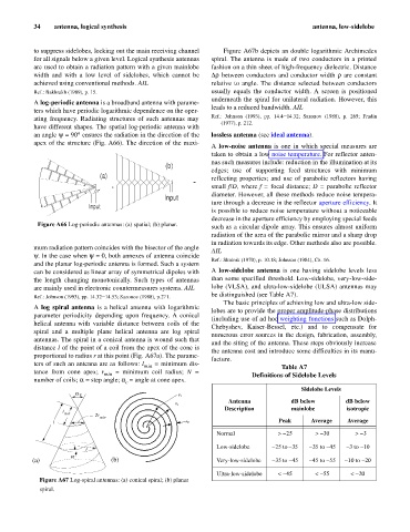
A log spiral antenna is a helical antenna with logarithmic
lobes are to provide the proper amplitude-phase distributions
parameter periodicity depending upon frequency. A conical
(including use of ad hoc weighting functions such as Dolph-
helical antenna with variable distance between coils of the
Chebyshev, Kaiser-Bessel, etc.) and to compensate for
spiral and a multiple plane helical antenna are log spiral
numerous error sources in the design, fabrication, assembly,
antennas. The spiral in a conical antenna is wound such that
and the siting of the antenna. These steps obviously increase
distance l of the point of a coil from the apex of the cone is
the antenna cost and introduce some difficulties in its manu-
proportional to radius r at this point (Fig. A67a). The parame-
facture.
ters of such an antenna are as follows: l min = minimum dis- Table A7
tance from cone apex; r min = minimum coil radius; N = Definitions of Sidelobe Levels
number of coils; a = step angle; a = angle at cone apex.
c
Sidelobe Levels
ac
r 1
Antenna dB below dB below
r 2
Description mainlobe isotropic
l
min 2r
min
l Dr Peak Average Average
Normal > -25 > -30 > -3
to
-3 -10
Low-sidelobe -25 to -35 -35 5 to
-4
r
a
to
to
to
(a) (b) Very-low-sidelobe -35 -45 -45 -55 -10 -20
Ultra-low-sidelobe < -45 < -55 < -20
Figure A67 Log-spiral antennas: (a) conical spiral; (b) planar
spiral.