
Page 46 - Radar Technology Encyclopedia
P. 46
36 antenna, omnidirectional antenna radiation regions
antenna noise temperature (see TEMPERATURE). A polarization-twist antenna is a dual-reflector antenna in
which the feed illuminates the first reflector, which consists
An omnidirectional antenna is one capable of providing
of wires matched to the feed polarization Fig. A71). Rays
360° coverage in the azimuth plane. Such antennas are typi-
from this wire grid are reflected to the second reflector, con-
cally used in electronic warfare systems. SAL
sisting of a solid surface overlaid with a grid (or ribs) at 45°.
Ref.: Neri (1991), p. 285.
Upon reflection from the second reflector, the polarization is
An optical antenna is one in which operation is based on rotated 90°to pass through the first reflector without block-
principles of geometrical optics. Optical antennas typically age.
include two subgroups: reflector antennas and lens antennas.
Grid at
SAL Horizontal Parabolic 45 o Solid flat
wire grid wire grid
Ref.: Skolnik (1990), p. 6.2. reflector
Parabolic surface
An “out-phasing” antenna is an auxiliary antenna or group V pol
V pol
V pol beam
beam
of antennas used with the basic antenna system to pick up l/4 beam l/4
jamming signals, as input to a sidelobe cancelation system in H pol Focal
horn
the receiver. SAL point H pol
horn
Ref.: Johnston (1979), p. 64. Grid at
45 o
antenna (radiation) pattern (see PATTERN, antenna).
patch antenna (see microstrip antenna).
(a) (b)
A pencil-beam antenna is one forming a pencil beam of cir- Figure A71 Polarization-twist parabolic antenna configurations:
cular cross section. These antennas typically are phased (a) Folded parabolic geometry, (b) mirror-scan geometry.
arrays or circular reflector antennas used in precision-track- In the configuration (a), the second reflector is a conven-
ing radars or multifunction phased array radars where a pencil tional parabolic surface, and the first reflector (grid) is a pla-
beam is used both for search and track functions. SAL nar surface which folds the focal point back to a region near
Ref.: Johnson (1993), p. 17.31; Skolnik (1980), p. 54. the center of the parabola, reducing the length of the feed line
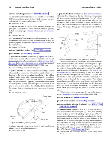
A pillbox antenna is a reflector antenna formed by a section and the mechanical inertia of the antenna, The inverse Cas-
of a paraboloid sandwiched between two parallel plates. Col- segrainian antenna shown previously in Fig. A51 uses the
limation of the beam in one plane is produced by the pillbox polarization-twist configuration shown in (b). The feed-horn
and collimation in the other plane is produced by a parabolic illuminates a wire-grid parabolic reflector, embedded in a
cylinder reflector (Fig. A70). Such an antenna is illuminated plastic cover in front of the antenna system. This reflects
by a waveguide or horn. Typically, this antenna is used when power back to the tilting plate, on which are a series of ribs
a narrow pattern in only one of the planes is desired. It can oriented at 45° to the incident polarization and l/4 deep, that
also be used as a linear feed for a highly elliptical reflector. rotate the linear polarization through 90° and reflect it as a
Sometimes these antennas are termed cheese-type antennas. beam which passes through the parabolic reflector and into
AIL space.
Polarization-twist antennas can also use either conven-
Ref.: Skolnik (1970), p. 10.13.
tional Cassegrainian or Gregorian configurations. DKB
Parallel plates
polyrod antenna (see dielectric antenna).
printed circuit antenna (see microstrip antenna).
antenna radiating element [radiator] (see RADIATING
ELEMENT, antenna).
Antenna radiation regions in front of an antenna are divided
Horn into (a) a near-field reactive region, (b) a near-field radiating
region, and (c) a far-field radiating region (Fig. A72). For
Parabolic measurement of antenna patterns, the normal criterion for far-
2
strip field conditions is R = 2D /l, where D is the diameter of the
f
Waveguide
antenna and l is the wavelength. Accurate measurement of
Figure A70 Pillbox [“cheese”] antenna. low sidelobe levels may require even greater distances from
the antenna. The actual power density along the axis of circu-
A planar antenna is one whose elements are located in one
lar aperture with taper to create -25-dB sidelobes is shown in
plane. It is also termed a flat antenna.
Fig. A73. (See also FIELD, antenna). DKB
Ref.: Fradin (1977), p. 184.
Ref.: Hansen (1964), pp. 24–46; Saad (1971), pp. 32–38; Johnson (1993),
p. 1-11.