
Page 40 - Radar Technology Encyclopedia
P. 40
30 antenna, dummy antenna gain
not included in signal generator is often called the dummy An antennafier is an antenna with an embedded amplifier.
antenna. SAL
A fixed-beam antenna is one without scanning or beam
Ref.: Johnston (1979), p. 58.
switching. Fixed-beam antennas are primarily used in elec-
tronic warfare systems, and the main types of such antennas
Paraboloidal are broadband dipoles, broadband monopoles, spirals (planar
main
reflector or conical), horns and slots, log periodics, helices, and reflec-
tor types. SAL
Ref.: Schleher (1986), pp. 474–482.
Hyperboloidal
subreflector frequency-independent antenna (see broadband antenna).
A fuselage-mounted antenna is an airborne radar transceiv-
Focus of
ing antenna installed along an aircraft fuselage on the inside
paraboloid
or in a special pod. It may or may not be used to generate a
Plane
synthetic aperture. One without synthetic aperture capability
wavefront
is a long antenna designed for observation of the terrain or
surface objects in accordance with the radiation pattern it
shapes. The antenna is attached in such a way that its beam is
perpendicular to the aircraft flight trajectory and surveillance
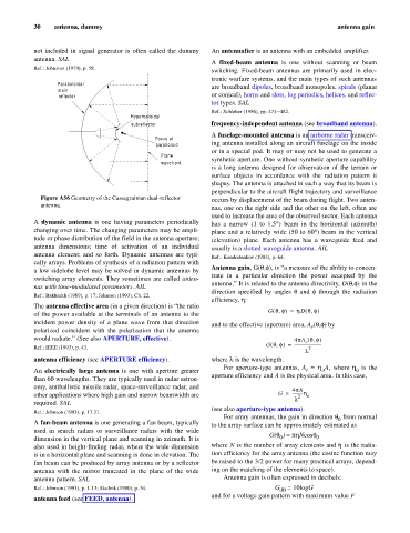
Figure A56 Geometry of the Cassegrainian dual-reflector occurs by displacement of the beam during flight. Two anten-
antenna.
nas, one on the right side and the other on the left, often are
used to increase the area of the observed sector. Each antenna
A dynamic antenna is one having parameters periodically has a narrow (1 to 1.5°) beam in the horizontal (azimuth)
changing over time. The changing parameters may be ampli- plane and a relatively wide (50 to 60° beam in the vertical
)
tude or phase distribution of the field in the antenna aperture; (elevation) plane. Each antenna has a waveguide feed and
antenna dimensions; time of activation of an individual usually is a slotted waveguide antenna. AIL
antenna element; and so forth. Dynamic antennas are typi-
Ref.: Kondratenkov (1983), p. 64.
cally arrays. Problems of synthesis of a radiation pattern with
,
)
Antenna gain, G(q,f is “a measure of the ability to concen-
a low sidelobe level may be solved in dynamic antennas by
trate in a particular direction the power accepted by the
switching array elements. They sometimes are called anten-
antenna.” It is related to the antenna directivity, D(q,f in the
)
nas with time-modulated parameters. AIL
direction specified by angles q and f through the radiation
Ref.: Bakhrakh (1989), p. 17; Johnson (1993), Ch. 22.
efficiency, h:
The antenna effective area (in a given direction) is “the ratio
G qf,( ) = h D qf)
(
,
of the power available at the terminals of an antenna to the
incident power density of a plane wave from that direction
and to the effective (aperture) area, A (q,f) by
r
polarized coincident with the polarization that the antenna
would radiate.” (See also APERTURE, effective). 4pA qf,( )
r
=
G qf,( ) ---------------------------
Ref.: IEEE (1993), p. 43. 2
l
antenna efficiency (see APERTURE efficiency). where l is the wavelength.
For aperture-type antennas, A = h A, where h is the
An electrically large antenna is one with aperture greater r a a
aperture efficiency and A is the physical area. In this case,
than 60 wavelengths. They are typically used in radar astron-
omy, antiballistic missile radar, space-surveillance radar, and 4pA
other applications where high gain and narrow beamwidth are G = ----------h a
2
l
required. SAL
(see also aperture-type antenna).
Ref.: Johnson (1993), p. 17.31.
For array antennas, the gain in direction q from normal
0
A fan-beam antenna is one generating a fan beam, typically
to the array surface can be approximately estimated as
used in search radars or surveillance radars with the wide
G(q ) » phNcosq 0
0
dimension in the vertical plane and scanning in azimuth. It is
also used in height-finding radar, where the wide dimension where N is the number of array elements and h is the radia-
is in a horizontal plane and scanning is done in elevation. The tion efficiency for the array antenna (the cosine function may
fan beam can be produced by array antenna or by a reflector be raised to the 3/2 power for many practical arrays, depend-
antenna with the mirror truncated in the plane of the wide ing on the matching of the elements to space).
antenna pattern. SAL Antenna gain is often expressed in decibels:
Ref.: Johnson (1993), p. 1-13; Skolnik (1980), p. 54. G = 10logG
dB
and for a voltage gain pattern with maximum value F
antenna feed (see FEED, antenna).