
Page 18 - Radar Technology Encyclopedia
P. 18
8 acquisition, reacquisition algorithm, Burg
ing based not only on designation sources but also on Ref.: Montgomery (1947), p. 336; Sazonov (1988), p. 57; Lavrov (1974), p.
information obtained during the previous acquisition process 331.
and subsequent tracking. This process of reacquisition is the A smooth adapter is one whose cross section changes
simplest for targets with highly predictable trajectory parame- smoothly. Essentially, smooth adapters are the extreme case
ters, such as satellites. In the case of a satellite, a relatively of stepped adapters with an unlimited increase in the number
short track with a precision radar can be used to generate of steps and a tendency toward zero in the length of each of
orbital elements for reacquisition of a satellite at its next revo- them. In type of frequency characteristic, a smooth adapter is
lution. SAL equivalent to a high-pass filter. Good matching is achieved in
Ref.: Barton (1964), p. 458. all frequencies above some boundary frequency.
A smooth adapter is preferable to a stepped adapter when
Single-scan acquisition probability is the probability of
the power to be transmitted is high. The minimum length of a
acquisition of the target on a single scan. The usual notion is
smooth adapter must be three to four times longer than the
P . If probability P is independent from scan to scan it is
a
a
defined and related to cumulative acquisition probability by: wave length in the line. IAM
Ref.: Montgomery (1947), p. 339; Sazonov (1988), p. 144; Rakov (1970),
1 k ¤ vol. 2, p. 246.
P = P P = ( 1 – P )
a v d c
A stepped adapter is one whose cross section changes in a
where P is the probability that the target lies within the scan
v
volume, P is the probability of target detection, P is the step-wise manner. The simple stepped adapter is a single-
c
d
required cumulative probability of acquisition, and k is the stage adapter with step length equal to one-fourth of the wave
length, the quarter-wave transformer, but it has limited band-
number of scans. SAL
width. Multistage adapters are used to extend the band. The
Ref.: Barton (1964), p.445, (1988), p. 455.
selected step length is the same, and the necessary shape of
Acquisition time is the time a radar needs to acquire a target the frequency matching characteristic is assured by selection
with the required acquisition probability. The usual notation of the wave resistances of the steps. A stepped adapter is
is t . During t the radar may perform one or more scans so equivalent to a bandpass filter. In comparison with a smooth
a
a
that the cumulative acquisition probability reaches the adapter, a stepped adapter has a shorter length with the identi-
required value. SAL cal wave resistances and mismatch tolerances, but is inferior
Ref.: Barton (1988), p. 451. to the smooth adapter in power handling capability. IAM
Ref.: Sazonov (1988), pp. 45, 140; Rakov (1970), vol 2., p. 246.
ADAPTER, microwave. A microwave adapter is a device
providing the connection between two transmission lines. ALGORITHM
One distinguishes between narrowband and wideband adapt-
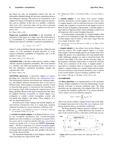
The Burg algorithm is an implementation of the maximum
ers, and adapters between transmission lines of one type or
entropy method technique to overcome disadvantage of poor
different types. When adapters are designed, attention is paid
spectral resolution in spectral estimation tasks. The Burg
to achieving high quality of transmission line matching over
algorithm uses the output data of the doppler filter (Fig. A18)
the frequency band while ensuring the required power han-
to estimate the feedback coefficients of an all-pole network,
dling capability. Based on the type of transmission line, there
whose output is given by difference equation:
are adapters between waveguides of various shapes (e.g.,
p
rectangular or round), coaxial waveguides, coaxial- and
(
Yn () = e n () + å a yn – k )
pk
waveguide-strip adapters, and others. These adapters, as a
k = 1
rule, are narrowband devices.
where Y(n) are the complex voltages at the N taps of the adap-
To match active loads, stepped and smooth adapters are
tive doppler processor; e(n) is the white noise sequence excit-
used between transmission lines of a single type, ensuring
ing the network, and a are the filter coefficients.
wideband matching for a given reflection coefficient. IAM pk
The Burg algorithm employs recursive relations to deter-
Ref.: IEEE (1993), p. 15; Montgomery (1947), Ch. 10; Sazonov (1988), pp.
mine the coefficients a , which determine the locations of
57, 140; Rakov (1970), vol. 2, p. 246. pk
poles in the transfer function. After these coefficients are esti-
A coaxial-waveguide adapter is an adapter between a coax-
ial and waveguide transmission line. Coaxial-waveguide Input
Tapped delay line
adapters provide excitation of a rectangular waveguide with a
H -wave, and of a round waveguide with a E -wave from a b 0 b 1 b 2 b Q
10
01
coaxial waveguide with a T-wave (see WAVE, electromag- S
netic). The basic component of a coaxial-waveguide adapter x(t)
a a a
is the pin, around which a current flows, which is located in a P P-1 1
waveguide short-circuited on one side, parallel to the lines of Tapped delay line
force of the electrical field.
The maximum bandwidth of such adapters reaches 20% Figure A18 General filter model (after Nitzberg, 1992, Fig. 11.7,
with a traveling-wave ratio of 0.95. IAM p. 297).