
Page 244 - Radar Technology Encyclopedia
P. 244
klystron, multiple-beam LENS 234
ing-wave structure. In contrast to the multibeam traveling- cavity grids and are modulated in speed, then move first in the
wave tube, the structure of the traveling wave in such a direction of the reflector, and then under the influence of its
klystron is at right angles to the beams rather than along them. braking field, in the opposite direction, and intersect the gab
The low supply power of the solenoid, which creates the between the resonator grids a second time. By this time the
focusing field, is another advantage of the multibeam electrons are grouped in clusters and in the braking phase of
klystron. Its drawbacks include its complexity and low reli- the variable voltage between the grids of the resonator, they
ability. give up their kinetic energy to the HF field of the cavity, and
Multibeam klystrons are usually used for supplying a through the output to the load.
group of phased-array antenna elements. IAM Reflex klystrons are used in the centimeter and millime-
Ref.: Skolnik (1970), p. 7-36; Andrushko (1981), p. 36. ter bands, usually as local oscillators of microwave receivers,
as measurement oscillators (see OSCILLATOR, klystron).
A multicavity [multiresonator] klystron is a floating-drift
An advantage of the reflex klystron is its electronic tunability
klystron with several (usually four or six) cavities. It is
(i.e., by changing the voltage at the reflector). IAM
marked by a high gain coefficient and high efficiency.
In the three-cavity klystron, in comparison with the two- Ref.: Popov (1980), p. 272; Andrushko (1981), p. 37; Gilmour (1986),
pp. 235-238.
cavity one, the efficiency is improved from 15 to 35%. A fur-
ther increase in the number of cavities does not lead to a sig-
nificant increase in the electronic efficiency, but increases the
gain coefficient (to 70 dB in the four-cavity klystron) and
changes the amplitude-frequency characteristic. Passbands up L
to 10% are achieved by detuning the cavities.
Multibeam klystrons are also often referred to as multi-
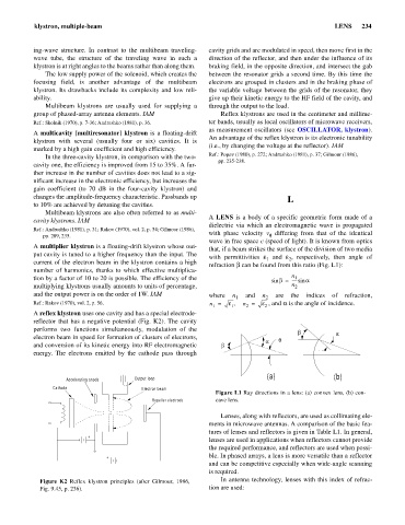
A LENS is a body of a specific geometric form made of a
cavity klystrons. IAM
dielectric via which an electromagnetic wave is propagated
Ref.: Andrushko (1981), p. 31; Rakov (1970), vol. 2, p. 54; Gilmour (1986),
with phase velocity v differing from that of the identical
pp. 209, 235. f
wave in free space c (speed of light). It is known from optics
A multiplier klystron is a floating-drift klystron whose out-
that, if a beam strikes the surface of the division of two media
put cavity is tuned to a higher frequency than the input. The
with permittivities e and e, respectively, then angle of
1
2
current of the electron beam in the klystron contains a high
refraction b can be found from this ratio (Fig. L1):
number of harmonics, thanks to which effective multiplica-
tion by a factor of 10 to 20 is possible. The efficiency of the sin b = n 1 a
----- sin
multiplying klystrons usually amounts to units of percentage, n 2
and the output power is on the order of 1W. IAM where n and n are the indices of refraction,
2
1
Ref.: Rakov (1970), vol. 2, p. 56. n = e n = e , and a is the angle of incidence.
,
1 1 2 2
A reflex klystron uses one cavity and has a special electrode-
reflector that has a negative potential (Fig. K2). The cavity
performs two functions simultaneously, modulation of the
b a
electron beam in speed for formation of clusters of electrons,
a q
and conversion of its kinetic energy into RF electromagnetic b
energy. The electrons emitted by the cathode pass through
(a) (b)
Accelerating anode Output loop
Cathode Electron beam
Figure L1 Ray directions in a lens: (a) convex lens, (b) con-
Repeller electrode cave lens.
Lenses, along with reflectors, are used as collimating ele-
ments in microwave antennas. A comparison of the basic fea-
tures of lenses and reflectors is given in Table L1. In general,
+
lenses are used in applications when reflectors cannot provide
the required performance, and reflectors are used when possi-
+ ble. In phased arrays, a lens is more versatile than a reflector
and can be competitive especially when wide-angle scanning
is required.
Figure K2 Reflex klystron principles (after Gilmour, 1986, In antenna technology, lenses with this index of refrac-
Fig. 9.45, p. 236). tion are used: