
Page 243 - Radar Technology Encyclopedia
P. 243
233 klystron, extended interaction klystron, multiple-beam
Table K1
Some Commercially Available High-Power Klystrons
Peak
Center
Peak power Frequency Max duty
Tube type frequency Gain (dB)
(MW) range (GHz) cycle Voltage Current
(GHz)
(kV) (A)
VA-1513 0.4–0.45 20 0.015 » 0.015 230 280 40
TV2023 1.3 40 1.2–1.4 0.001 300 230 53
F2049 2.856 30 Fixed 0.008 290 295 50
VKS-8262 2.9 5.5 0.005 0.001 125 88 50
SAC42 5.65 3.3 5.4–5.9 0.002 135 112 23.5
SAX191 9.015 1.25 8.83–9.2 0.0048 85 50 50
(from Ewell, 1981, Table 2-6, p. 61, reprinted by permission of McGraw-Hill).
An extended interaction klystron uses an output circuit with between the input and output cavities, the system operates as
extended interaction, which has several interaction spaces for an oscillator with self-excitation.
extraction of beam energy. Such an output circuit may be To increase the output power, the floating-drift klystron
viewed as a series of successive and interrelated cavities, each is made as a multicavity klystron, with several parallel elec-
of which is associated with the beam. As a result, the effi- tron beams, each of which is formed by its electron gun.
ciency and bandwidth are increased. However, since there is a Floating-drift klystrons can operate either in the continu-
connection between several zones in a chain of extended ous or in the pulse mode. Powerful pulsed floating-drift
interaction cavities, and each of them is connected to the klystrons are used in radar amplifiers and oscillators,
beam, it is hard to obtain oscillations in the traveling-wave charged-particle accelerators, and so forth. Continuous-wave
mode. IAM floating-drift klystrons are used on microwave communica-
Ref.: Gilmour (1986), pp. 203, 235, 315-316; Skolnik (1970), p. 7-34. tions systems. IAM
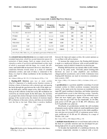
A floating-drift klystron uses two or more cavities Ref.: Popov (1980), p. 324; Andrushko (1981), p. 36; Rakov (1970), vol. 2,
p. 51.
(Fig. K1). Operation of a double-cavity klystron consists of
forming a beam of electrons with a electron gun and passing A gyroklystron is a gyrotron amplifier consisting of several
the beam through the gap between the walls of the input cav- resonant cavities in which cyclotron resonance interaction
ity, the drift space, and the output cavity, after which the elec- occurs. At the input cavity the electrons are modulated by the
trons go to the collector. In the first cavity, RF oscillations are input RF signal resulting in bunching, and further interaction
excited by an external signal. In the drift space, the electrons and amplification occurs in the following cavities. Typically,
are grouped into clusters through velocity modulation. During gyroklystrons are designed to operate in the millimeter-wave
passage of the second cavity, the clusters of electrons impart band and have higher gain, higher efficiency, and higher
RF oscillations of the same velocity, and these are transmitted power than the gyro-TWT but less bandwidth. At 28 GHz,
over the line to the load. When there is positive feedback peak power of 65 kW, gain of 30 dB, 10% efficiency, and
0.2% bandwidth were achieved.
Input Output
Drawbacks of gyroklystrons include the self-excitation
of parasitic modes and the relatively small amplification band
(no more than 1%). The output power in the stable amplifica-
tion ode does not exceed 65 kW of continuous power with a
Collector
Drift gain coefficient of 40 dB and 9% efficiency in a range of
space
28 GHz. SAL, IAM
Ref.: Currie (1987), p. 469; Gilmour (1986), p. 430.
A multiple-beam klystron uses several beams and cavities in
the form of a periodic structure and was developed for pro-
ducing high power at a given operating voltage.
Figure K1 Double-cavity, floating-drift klystron (after Rakov, To broaden the bandwidth of a multibeam klystron, the
1970, Fig. 1.19, p. 49). resonance nonperiodic structure is replaced with a travel-