
Page 246 - Radar Technology Encyclopedia
P. 246
lens, computing lens, metal-plate 236
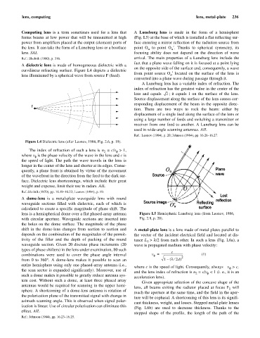
Computing lens is a term sometimes used for a lens that A Luneburg lens is made in the form of a hemisphere
forms beams at low power that will be transmitted at high (Fig. L5) at the base of which is installed a flat reflecting sur-
power from amplifiers placed at the output (element) ports of face ensuring a mirror reflection of the radiation source from
the lens. It can take the form of a Luneburg lens or a bootlace point O to point O ¢. Thanks to spherical symmetry, its
u
u
lens. SAL focusing ability does not depend on the direction of wave
Ref.: Skolnik (1980), p. 316. arrival. The main properties of a Luneburg lens include the
fact that a plane wave falling on it is focused at a point lying
A dielectric lens is made of homogeneous dielectric with a
on the opposite side of the surface and, consequently, a wave
curvilinear refracting surface. Figure L4 depicts a dielectric
from point source O ¢ located on the surface of the lens is
u
lens illuminated by a spherical wave from source F (feed).
converted into a plane wave during passage through it.
A Luneburg lens has a variable index of refraction. The
index of refraction has the greatest value in the center of the
lens and equals 2 ; it equals 1 on the surface of the lens.
Source displacement along the surface of the lens causes cor-
responding displacement of the beam in the opposite direc-
F
tion. There are two ways to rock the beam: either by
displacement of a single feed along the surface of the lens or
using a large number of feeds and switching a transmitter or
receiver from one feed to another. A Luneburg lens can be
used in wide-angle scanning antennas. AIL
Ref.: Leonov (1984), p. 20; Johnson (1984), pp. 16.26–16.27.
Figure L4 Dielectric lens (after Leonov, 1986, Fig. 2.6, p. 19).
The index of refraction of such a lens is n = c/v > 1,
f
2
where v is the phase velocity of the wave in the lens and c is
f
the speed of light. The path the wave travels in the lens is
longer in the center of the lens and shorter at its edges. Conse-
quently, a plane front is obtained by virtue of the movement
of the wavefront in the direction from the feed to the dark sur-
face. Dielectric lens shortcomings, which include their great
weight and expense, limit their use in radars. AIL
Ref.:Skolnik (1970), pp. 10.19–10.22; Leonov (1984), p. 19.
A dome-lens is a metal-plate waveguide lens with round
waveguide sections filled with dielectric, each of which is
calculated to create a specific magnitude of phase shift. The
lens is a hemispherical dome over a flat phased-array antenna Figure L5 Hemispheric Luneburg lens (from Leonov, 1986,
with circular aperture. Waveguide sections are inserted into Fig. 2.8, p. 20).
the holes on the dome surface. The magnitude of the phase
shift in the dome-lens changes from section to section and A metal-plate lens is a lens made of metal plates parallel to
depends on the combination of the magnitudes of the permit- the vector of the incident electrical field and located at dis-
tivity of the filler and the depth of packing of the round tance L > l/2 from each other. In such a lens (Fig. L6a), a
1
waveguide section. Given 20 discrete phase increments (20 wave is propagated medium with phase velocity:
types of phase shifters) in the lens under examination, 80 such c
combinations were used to cover the phase angle interval v = ---------------------------------- 2 (1)
f
¤
from 0 to 360° A dome-lens makes it possible to scan an 1 – ( l 2d )
.
entire hemisphere using only one phased-array antenna (i.e.,
where c is the speed of light. Consequently, always v > c,
f
the scan sector is expanded significantly). Moreover, use of
and the lens index of refraction is n = c/v < 1 (i. e., it is an
2
f
such a dome makes it possible to greatly reduce antenna sys-
acceleration lens).
tem cost. Without such a dome, at least three phased array
Given appropriate selection of the concave shape of the
antennas would be required for scanning in the upper hemi-
lens, all beams exiting the radiator placed at focus F will
1
sphere. A shortcoming of a dome-lens antenna is rotation of
reach the aperture at the same time, and the field in the aper-
the polarization plane of the transmitted signal with change in
ture will be cophasal. A shortcoming of this lens is its signifi-
azimuth scanning angle. This is observed when signal polar-
cant thickness, weight, and losses. Stepped metal-plate lenses
ization is linear. Use of circular polarization can eliminate this
(Fig. L6b) are used to decrease thickness. Thanks to the
effect. AIL
stepped shape of the profile, the length of the path of the
Ref.: Johnson (1984), pp. 16.23–16.25.