
Page 250 - Radar Technology Encyclopedia
P. 250
limiter, transistor lobing, sequential 240
Power limiters are designed for a power on the order of a multipath (propagation) lobing (see PROPAGATION).
Watt, and their output stages can be built in a balance circuit.
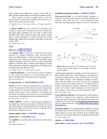
Lobe-on-receive-only is an angle-tracking technique in
These limiters are used to equalize power in the fre-
which the receiving beam pattern is switched between two
quency band in exciter-local oscillators and microwave cir-
positions offset from the axis of the transmitted beam
cuits of special radio receivers. IAM
(Fig. 10a). The target position relative to the axis is sensed by
Ref.: Skolnik (1970), p. 5.38; Gassanov (1988), p. 145; Grigor’yants (1981),
p. 65.
A varactor limiter uses the variation of capacitance with Receive lobe
Target
voltage to realize power limiting at microwave frequencies.
The input signal experiences low loss until it reaches some
threshold value, after which the output will remain constant Transmit lobe
until a second threshold is reached. Beyond the second Radar
Receive lobe
threshold the output power increases with input, but the loss
is large. DKB
Ref.: Gardiol (1984), p. 310.
(a)
LINE
delay line (see DELAY LINE).
The long-line effect is the effect of distortions that can be LO
produced by multiple reflections along transmission-line Beam 1 IF amp Store
1
paths. In wideband radars, a single mismatch in nondispersive Env D/S
det
transmission line reduces the amount of transmitted signal Beam 2 Store + S
without introducing distortion, and two or more mismatches 2 To display
produce a nonlinear phase variation with frequency because (b)
of the interference caused by superposition of resulting waves
Figure L10 Lobe-on-receive-only tracking system: (a) trans-
traveling in the same direction. SAL mit and receive beam patterns, (b) processing system for
Ref.: Skolnik (1970), p. 7.13; Wehner (1987), pp. 60–64. received signals.
A pulse-forming line is a network used in radar modulators comparing the amplitudes of signals received successively on
to store energy and release it to the transmitting tube in a the two lobes (Fig. L10b). The technique can be applied to a
pulse of predetermined width and constant amplitude. conically scanning receive beam, in which case it is some-
Ref.: Glasoe (1948), Ch. 7. times called conopulse. The advantage of lobing-on-receive-
only is that the lobing rate cannot be sensed by a jamming
transmission line (see TRANSMISSION LINE).
system, and hence the jammer must use a technique such as
LOAD. A load is “a power consuming device connected to a barrage scan-frequency jamming, dispersing its modulation
circuit.” If any element of the circuit is removed (temporarily power over a band of audio frequencies to cover the actual
or permanently) the artificial termination that replaces it is scan frequency with at least some AM components. DKB
termed a dummy load, which is defined as “a dissipative but Ref. Barton (1988), p. 420.
essentially nonradiating substitute device having impedance
Lobe [sidelobe] reduction is the technique by which undesir-
characteristics simulating those of the substituted device.”
able lobes in response of an antenna or pulse-compression
Ref.: IEEE (1993), pp. 393, 730.
system are reduced. Tapering of the aperture illumination and
LOBE, LOBING. A lobe is a response peak, generally hav- weighting of the signal spectrum are the principal techniques
ing symmetric curvature, in any radar coordinate. The term is used for sidelobe reduction. (See APERTURE illumination;
most often applied to antenna patterns, but can also be used to WEIGHTING.)
describe the output waveform of a receiver, especially one in Sequential lobing is the angle-tracking technique in which
which pulse compression is used. the antenna lobe is moved between two or more positions in
rapid sequence to sense target position. Lobe switching and
antenna (pattern) lobe (see PATTERN, antenna).
conical scan are the principal types of sequential lobing. DKB
grating lobes (see PATTERN, array). Ref.: Barton (1988), p. 383.
The mainlobe is an antenna lobe in the direction of maximum sidelobe (see SIDELOBE).
gain. SAL
silent lobing (see lobe-on-receive-only; TRACKING).
Ref.: Johnson (1984), p. 1.13.