
Page 255 - Radar Technology Encyclopedia
P. 255
245 LOSS, in radar loss, antenna
where D is the basic detectability factor for integration of n
Table L5
pulses using the fluctuation model for the target. The transmit
Receiver-Processor Loss Factors (Type 4)
line loss L , pattern-propagation factor F, and atmospheric
t
attenuation L , are included separately in the standard range
a
Component Symbol Note
equation and in the Blake chart. (See RANGE EQUATION.)
Blind phase loss L mti(b) 6, 8 DKB, SAL
Ref.: Blake (1980), Ch. 2; Skolnik (1980), p. 56; Barton (1988), pp. 574–575,
Noise correlation loss L mti(a) 6, 8 (1993), pp. 130–137.
Velocity response loss L mti(c) 6, 8 Angle straddling loss is the result of batch processing in the
integration process of pulse or samples received by a scan-
Operator [display] loss L o 6, 8 ning radar, such that the available target energy is split
between two contiguous batches. The loss is defined as the
Pulse width loss L pw 6, 8
increase in input signal energy required to achieve a given
Quantizing loss L q 6, 8 detection performance on targets appearing randomly in
angle, compared with that required for a target echo centered
Range cusping loss L er 6, 8 within a single batch. The loss depends on the ratio of the
Scan distribution loss L d 10 batch duration (integration time t ) to the observation time
sb
(time-on-target) t , the target fluctuation model, and on the
o
Straddling losses:
required detection probability. Figure L15 shows the loss for
Angle straddling loss L ea 6, 8
Doppler filter straddling loss L ef 6, 8
Range gate (or strobe) straddling loss L er 6, 8
Notes for Tables 2 through 5:
1 Included in calculation of antenna gain G
2 Included in calculation of system noise temperature T s
3 Included in calculation of pattern-propagation factor F
4 Used in calculation of tracking error
5 Included in calculation of detectability factor D
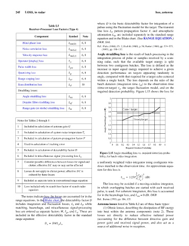
Figure L15 Angle straddling loss vs. required detection proba-
6 Included in miscellaneous signal processing loss L x bility, for batch video integration.
7 Consider possible differences between losses for signal and a uniformly weighted video integrator using contiguous win-
clutter; effective S/C may or may not be affected dows matched to the observation time. An approximate equa-
tion for this loss is
8 Losses do not apply to clutter power; effective S/C is
1
2
reduced by these losses --- 3 æ t sb ö
L = 1.25P ------ (dB)
ea d è t ø
9 Included as separate term in conventional range equation o
The loss may be avoided if a moving-window integrator,
10 Loss included only in search loss factor of search radar
in which overlapping batches are started with each received
equation
pulse, is used. For coherent integration, this loss is accounted
for in the beamshape loss, and L = 0 dB. DKB
The notes indicate how the losses are accounted for in the ea
range equations. In the Blake chart, the detectability factor D Ref.: Barton (1993), pp. 104, 133.
includes integration and fluctuation losses, L and L , while Antenna losses listed in Table L2 are of three basic types:
f
i
matching, beamshape, and miscellaneous signal-processing (1) Ohmic losses, describing the dissipation of RF energy
loss are entered as separate factors M, L , and L . These are into heat within the antenna components (note 2). These
x
p
included in the effective detectability factor in the standard losses act directly to reduce effective radiated power
range equation: (accounting for the difference between directive gain and
D = DML L power gain) and received signal power, and also act as a
x
p x
source of additional noise in reception.