
Page 256 - Radar Technology Encyclopedia
P. 256
loss, antenna loss, antenna pattern factor 246
(2) Nonohmic losses in mainlobe (on-axis) gain, describ-
ing factors that spread the radiation pattern (notes 1, 10).
These affect both directive and power gain.
(3) Factors that prevent the full on-axis gain of the
antenna from being brought to bear on the target (notes 3, 4).
These factors are normally included in the pattern-propaga-
tion factor and are dependent on the target position relative to
the beam (and on target and antenna polarizations).
The treatment of these losses in the radar equation is indi-
cated by the notes to the tables. In the case of the beamwidth
factor, it applies only to the search radar equation, and results
from the assumption there that the transmit antenna gain can
be replaced with the term 4p/q q .
a e
The total antenna loss describes the reduction in antenna
power gain G relative to G for the ideal (uniformly illumi-
0
nated (lossless) antenna of the same aperture area A. This loss
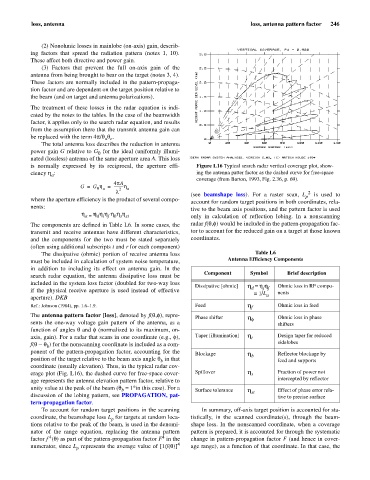
is normally expressed by its reciprocal, the aperture effi- Figure L16 Typical search radar vertical coverage plot, show-
ciency h : ing the antenna patter factor as the dashed curve for free-space
a
coverage (from Barton, 1993, Fig. 2.36, p. 69).
4pA
G = G h = ----------h
0 a 2 a
l 2
(see beamshape loss). For a raster scan, L is used to
p
where the aperture efficiency is the product of several compo-
account for random target positions in both coordinates, rela-
nents:
tive to the beam axis positions, and the pattern factor is used
h hh h h h
h a = d i f b s st only in calculation of reflection lobing. In a nonscanning
The components are defined in Table L6. In some cases, the radar f(q,f) would be included in the pattern-propagation fac-
transmit and receive antennas have different characteristics, tor to account for the reduced gain on a target at those known
and the components for the two must be stated separately coordinates.
(often using additional subscripts t and r for each component)
The dissipative (ohmic) portion of receive antenna loss Table L6
must be included in calculation of system noise temperature, Antenna Efficiency Components
in addition to including its effect on antenna gain. In the
Component Symbol Brief description
search radar equation, the antenna dissipative loss must be
included in the system loss factor (doubled for two-way loss
Dissipative [ohmic] h = hh Ohmic loss in RF compo-
f f
d
if the physical receive aperture is used instead of effective
= 1/L a nents
aperture). DKB
Ref.: Johnson (1984), pp. 1.6–1.9. Feed h f Ohmic loss in feed
),
The antenna pattern factor [loss], denoted by f(q,f repre- Phase shifter h Ohmic loss in phase
sents the one-way voltage gain pattern of the antenna, as a f shifters
function of angles q and f (normalized to its maximum, on-
axis, gain). For a radar that scans in one coordinate (e.g., f), Taper [illumination] h i Design taper for reduced
) for the nonscanning coordinate is included as a com-
f(q - q sidelobes
b
ponent of the pattern-propagation factor, accounting for the Blockage h Reflector blockage by
position of the target relative to the beam axis angle q in that b feed and supports
b
coordinate (usually elevation). Thus, in the typical radar cov-
erage plot (Fig. L16), the dashed curve for free-space cover- Spillover h s Fraction of power not
age represents the antenna elevation pattern factor, relative to intercepted by reflector
unity value at the peak of the beam (q = 1°in this case). For a Surface tolerance h Effect of phase error rela-
b
discussion of the lobing pattern, see PROPAGATION, pat- st tive to precise surface
tern-propagation factor.
To account for random target positions in the scanning In summary, off-axis target position is accounted for sta-
coordinate, the beamshape loss L for targets at random loca- tistically, in the scanned coordinate(s), through the beam-
p
tions relative to the peak of the beam, is used in the denomi- shape loss. In the nonscanned coordinate, when a coverage
nator of the range equation, replacing the antenna pattern pattern is prepared, it is accounted for through the systematic
4
4
factor f (q) as part of the pattern-propagation factor F in the change in pattern-propagation factor F (and hence in cover-
numerator, since L represents the average value of [1/f(q)] 4 age range), as a function of that coordinate. In that case, the
p