
Page 259 - Radar Technology Encyclopedia
P. 259
249 loss, beamshape loss, blind-phase
scan occurs in one coordinate, the random off-axis position of
the target in the other coordinate appears as a reduction in the
antenna pattern factor. P d = 0.99 P d = 0.9 P d = 0.8
The beamshape loss was originally calculated as the 12 P = 0.7
d
reciprocal of the integrated power received by the antenna for
scatterers distributed uniformly in angle, relative to that of an 10
idealized rectangular beam matched to the one-way, half- P = 0.6
power beamwidths of the actual antenna: 8 d
1 1 4 Beamshape loss (dB)
[
d d
----- = ----------- ò ò f qf,( )] q f 6
2 q q
L p a e 4p P = 0.5
d
In that form, it accounts for the clutter power received from a 4
uniform cloud filling the region in both coordinates around 2
the beam, as in radar meteorology, and that is the appropriate
definition for volume clutter power calculations. When 0
0 0.5 1 1.5 2
applied to the range equation for target detection by scanning
Samples per beamwidth, 1/n
radar, however, it is not sufficient to increase the on-axis
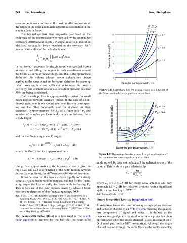
power by this constant loss unless detection probabilities near Figure L20 Beamshape loss for a steady target as a function of
50% are being considered. the beam motion between pulses or scan lines.
The beamshape loss is approximately constant for small
beam motion between samples (pulses, in the case of a con- 10
tinuous rapid scan in one coordinate, scan lines or beam spac- 9
ing for the other coordinate and for discrete, or step, 8 P = 0.7
d
scanning). Approximations for L as a function of P and 7
p d P = 0.6
d
number of samples per beamwidth n are as follows, for a 6
steady target: Beamshape loss (dB) 5 P d = 0.8
– 3 4
(
=
L n () 1.2 + 4.5 P – 0.4 )n (dB), P ³× d 0.4 3
p
d
– 3 2
(
= 1.2 + 1.35 P – 0.4 )n (dB), P <× 0.4 P = 0.5
d
d d 1 = 0.9 = 0.99
and for the fluctuating (case 1) target: 0 P d P d
1
2
– 0.03L f ¢ 0 0.5 1 1.5 2
L ¢n () 10= × L n () 0.4L ¢ (dB)+
p p f
Samples per beamwidth, 1/n
where the fluctuation loss approximation is
Figure L21 Beamshape loss for a case 1 target as a function of
2 the beam motion between pulses or scan lines.
L ¢= – 8.4log ( 1 – P ) 3.0 1 –– ( P ) (dB)
f
d
d
angle y = q q does not include all the radiated power of the
e a
b
Using these approximations, the beamshape loss is given in pattern. This leads to a gain relationship
Figs. L20 and L21 as a function of the beam motion between 4p
pulses (or scan lines), for different probabilities of detection. G = -----------------
t
q q L
e a n
It can be seen that the loss increases rapidly for a steady
target as P and beam motion increase, but that for the fluctu-
d
n
ating target the loss actually decreases with increasing P . where L » 1.2 = 0.8 dB for many array antennas and may
d
This is because of the contributions made by adjacent beam approach 1.6 = 2 dB for reflector systems having significant
spillover and blockage. DKB
positions to detection of the fluctuating target. DKB
Ref.: Barton (1969), p. 334.
Ref.: Blake, L. V., “The Effective Number of Pulses per Beamwidth for a
Scanning Radar,” Proc. IRE 41, no. 6, June 1953, pp. 770–774; Hall, W. binary integration loss (see integration loss).
M., and Barton, D. K., “Antenna Pattern Loss Factor for Scanning
Radars,” Proc. IEEE 53, no. 9, Sept. 1965, pp. 1257–1258; Hall, W. M., Blind-phase loss is the result of using a single phase detector
“Antenna Beam-Shape Factor in Scanning Radars,” IEEE Trans. AES-4, and canceler channel in an MTI system, rejecting the quadra-
no. 3, May 1968, pp. 402–409.
ture components of signal and noise. It is defined as the
The beamwidth factor [loss] is a loss used in the search increase in signal power required to achieve a given detection
radar equation to account for the fact that the beam solid performance when the single channel is used instead of an I-
Q channel pair (vector MTI processing). Although the single
channel has, on average, the same SNR as the vector canceler,