
Page 262 - Radar Technology Encyclopedia
P. 262
loss, crossover loss, field degradation 252
tion for tracking error of a conical scan radar (see accuracy lobe level, for different families of weighting. In this case the
of sequential lobing). DKB loss is also termed weighting loss. DKB
Ref.: Barton (1988), p. 387. Ref.: Barton (1969), App. B.
Detector loss results from passing a signal at finite S/N Duplexer loss is a component of the transmit and receive line
through an envelope detector, or in a monopulse tracker from losses, resulting from attenuation in passage of the signal
using the sum channel signal at finite S/N as the reference in a through the duplexer.
phase-sensitive error detector. For detection calculations, the
Eclipsing loss is the result of signal arrival during the trans-
detector loss may be modeled as C = 1 + 2.3N/S. The video mission of a pulse, either from targets beyond the first range
x
integration loss is a direct result of detector loss, and may be
interval R = c/2f in a medium- or high-PRF radar, or within
r
u
calculated as L (n) = C (n)/C (1), where C (n) applies to the that interval at ranges within one pulse length ct/2 of zero
x
i
x
x
reduced S/N value made possible by integration, and C (1) is range or R . The loss is defined as the increase in signal
x
the value that would apply for the S/N of a single pulse giving u
energy required to obtain a given detection performance, rela-
the same detection performance. The loss C (1) reflects the tive to that required for target signals that are received during
x
difference between detection performance with the envelope
times the transmitter is off. In medium- and high-PRF radars
detector and that with a coherent detector (known signal
using PRF diversity to avoid eclipsing and blind regions, the
phase). DKB
average loss in received energy, indicative of the eclipsing
Ref.: Barton (1988), pp. 64, 467.
loss for P » 0.5, may be estimated as the reciprocal of the
d
Display loss describes the loss in detection performance, rela- fraction of the pulse repetition interval which is not occupied
tive to the theoretical performance of an optimum detector, by the transmission:
when target detection is performed by an operator viewing a 1
CRT display. Factors causing this loss are (1) insufficient L ec = --------------- r
1 –
t f
dynamic range in the receiver or video circuits, (2) inadequate
brightness of the display, (3) defocusing of the CRT (a form where t is the transmitted pulse width and f is the PRF. For
r
of collapsing loss), (4) nonoptimum displayed pulse widths, any given PRF, pulse width, and signal delay, the loss may be
(5) insufficient noise deflection or intensity on the display, calculated as the ratio of processor signal output power to that
(6) excessive numbers of resolution elements on the display, obtained on a pulse in the clear region. DKB
(7) crowding of data in the region near the center of a PPI dis- Barton (1988), p. 270.
play, and (8) operator fatigue (usually considered separately
Faraday rotation loss occurs when the radar wave travels
as operator loss. DKB
through the ionosphere, interacting with the earth’s magnetic
Ref.: Nathanson (1969), pp. 100–106.
field (see ANGLE, Faraday rotation). Because the rotation
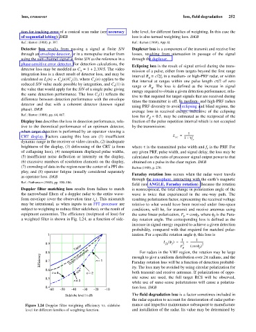
Doppler filter matching loss results from failure to match is nonreciprocal, the total change in polarization angle of the
the narrowband filters of a doppler radar to the entire wave- wave is twice that experienced in the one-way path. The
form envelope (over the observation time t ). This mismatch resulting polarization factor, representing the received voltage
o
may be intentional, as when inputs to an FFT processor are relative to what would have been received under free-space
subject to weighting to reduce filter sidelobes), or the result of conditions, will be, for transmit and receive antennas using
equipment economies. The efficiency (reciprocal of loss) for the same linear polarization, F = cosf, where f is the Fara-
f
f
p
a weighted filter is shown in Fig. L24, as a function of side- day rotation angle. The corresponding loss is defined as the
increase in signal energy required to achieve a given detection
probability, compared with that required for matched polar-
1 ization. For a specific rotation angle f, this loss is
1 1
L () ------ = ---------------------
f =
0.9 fp f 2 ( f )
2
Taylor F p cos f
0.8 For radars in the VHF region, the rotation may be large
Efficiency 0.7 Dolph-Chebyshev n = 1 enough to give a uniform distribution over 2p radians, and the
Faraday rotation loss will be a function of detection probabil-
0.6 n ity. The loss may be avoided by using circular polarization for
n = 4 cos n = 2 both transmit and receive antennas. If polarizations of oppo-
site sense are used, the full target RCS will be observed,
0.5
n = 3
while use of same-sense polarizations will cause a polariza-
0.4 tion loss. DKB
60 50 40 30 20 10
Sidelobe level in dB The field degradation loss is a factor sometimes included in
the radar equation to account for deterioration of radar perfor-
Figure L24 Doppler filter weighting efficiency vs. sidelobe mance and imperfect maintenance subsequent to manufacture
level for different families of weighting function. and installation of the radar. Its value may be determined by