
Page 265 - Radar Technology Encyclopedia
P. 265
255 loss, limiter [limiting] loss, radome
lens(-effect) loss (see atmospheric lens loss). traction by external factors, nonoptimum displays and
lighting, and similar effects. No precise data on operator loss
Limiter [limiting] loss results from passing the signal
exists, but estimates from 3 to 10 dB are often applied. DKB
through a hard limiter at intermediate frequency before fur-
ther processing. This loss is applicable to certain types of pattern-propagation [loss] factor (see PROPAGATION,
CFAR processor, such as the Dicke fix. The loss is equal to 4/ pattern-propagation factor).
p or 1.05 dB. DKB
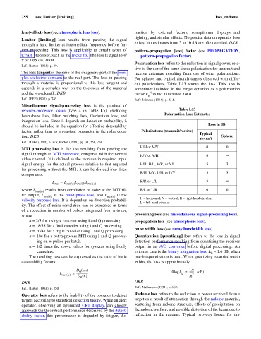
Polarization loss refers to the reduction in signal power, rela-
Ref.: Barton (1988), p. 89.
tive to the use of the same linear polarization for transmit and
The loss tangent is the ratio of the imaginary part of the com- receive antennas, resulting from use of other polarizations.
plex dielectric constant to the real part. The loss in passing For spheres and typical aircraft targets observed with differ-
through a material is proportional to this loss tangent and ent polarizations, Table L13 shows the loss. This loss is
depends in a complex way on the thickness of the material sometimes included in the range equation as a polarization
4
and the wavelength. DKB factor F in the numerator. DKB
p
Ref.: IEEE (1993), p. 745. Ref.: Johnson (1984), p. 23.8.
Miscellaneous signal-processing loss is the product of
receiver-processor losses (type 4 in Table L5), excluding Table L13
Polarization Loss Estimates
beamshape loss, filter matching loss, fluctuation loss, and
integration loss. Since it depends on detection probability, it
Loss in dB
should be included in the equation for effective detectability
factor, rather than as a constant parameter in the radar equa- Polarizations (transmit/receive)
Typical
tion. DKB Sphere
aircraft
Ref.: Blake (1980), p. 378; Barton (1988), pp. 31, 250, 268.
H/H or V/V 0 0
MTI processing loss is the loss resulting from passing the
signal through an MTI processor, compared with the normal H/V or V/H 6 ¥
video channel. It is defined as the increase in required input
signal energy for the actual process relative to that required H/R, H/L, V/R, or V/L 3 3
for processing without the MTI. It can be divided into three
R/H, R/V, L/H, or L/V 3 3
components:
L
L mti = L mti(a) mti(b) mti(c) R/R or L/L 3 ¥
L
where L mti(a) results from correlation of noise at the MTI fil- R/L or L/R 0 0
ter output, L mti(b) is the blind-phase loss, and L mti(c) is the
velocity response loss. It is dependent on detection probabil- H = horizontal, V = vertical, R = right-hand circular,
L = left-hand circular
ity. The effect of noise correlation can be expressed in terms
of a reduction in number of pulses integrated from n to an,
where processing loss (see miscellaneous signal-processing loss).
a = 2/3 for a single canceler using I and Q processing. propagation loss (see atmospheric loss).
a = 18/35 for a dual canceler using I and Q processing.
pulse width loss (see array bandwidth loss).
a = 20/47 for a triple canceler using I and Q processing.
a = 1/m for a batch-process MTI using I and Q process- Quantization [quantizing] loss refers to the loss in signal
ing on m pulses per batch. detection performance resulting from quantizing the receiver
a = 1/2 times the above values for systems using I-only output in an A/D converter before digital processing. An
cancelers. extreme case is the binary integration loss, L » 1.6 dB, when
b
The resulting loss can be expressed as the ratio of basic one-bit quantization is used. When quantizing is carried out to
detectability factors: m bits, the loss is approximately
D an ) 1.6
(
------- (dB)
0
q
L mti a () = ------------------ 10log L = 2
D n ()
0 m
DKB DKB
Ref.: Nathanson (1991), p. 662.
Ref.: Barton (1988), p. 250.
Operator loss refers to the inability of the operator to detect Radome loss refers to the reduction in power received from a
targets according to statistical detection theory. While an alert target as a result of attenuation through the radome material,
operator, observing an optimized CRT display, can closely scattering from radome structure, effects of precipitation on
approach the theoretical performance described by the detect- the radome surface, and possible distortion of the beam due to
ability factor, this performance is degraded by fatigue, dis- refraction in the radome. Typical two-way losses for dry