
Page 269 - Radar Technology Encyclopedia
P. 269
259 magnetron, coaxial magnetron, inverted-coaxial
A dither-tuned magnetron is a mechanically tuned magne-
tron with an integral motor and resolver to provide frequency-
agile operation. A voltage output from a resolver, propor-
tional to the magnetron frequency, is used to adjust the
receiver local oscillator to track the rapidly tuned frequency
of the magnetron. Such type of magnetron is capable of rapid
tuning over a narrow band and also can be tuned to a fre-
quency over a broad band in the normal manner using a
geared drive. With servo-motor control it is possible to go
from one frequency to another under 0.1 sec. Attainable tun-
ing range and tuning rates are restricted by mechanical limita-
tions imposed by acceleration forces.
Dither-tuning of coaxial magnetrons may also be
obtained using an element termed a ring tuner, which consists
Figure M1 Cross-sectional sketch of the coaxial cavity magne-
tron (from Skolnik, 1980, Fig. 6.3, p. 194, reprinted by permis- of a narrow ring. This ring is installed in an annular groove
sion of McGraw-Hill). cut into the outer wall of the cavity, and projects slightly into
the cavity. By deforming the ring inward from mechanical
A continuous-wave magnetron operates in the CW mode. motion applied to the ends of the ring, the frequency in the
The efficiency of such devices is about 30%, power levels are cavity is changed. SAL
few hundred watts. The range of application is primarily in Ref.: Skolnik (1980), p. 200; Fink (1975), p. 9.53.
doppler radar and electronic countermeasure systems. SAL
A frequency-agile magnetron provides a variable output fre-
Ref.: Ewell (1981), p. 33; Fink (1975), p. 9.50.
quency by changing the resonant frequency of its cavity. In
A conventional magnetron is the classical structure general there are two basic approaches to change the magne-
(Fig. M2) in which the anode is a large block of copper (1) tron frequency: electronic tuning and mechanical tuning.
with holes (2) and slots (3), the latter function as the resonant Magnetrons using the first approach are termed voltage-tuned
circuits. The holes correspond roughly to inductors, and the magnetrons, and those which use the second one are called
slots to capacitors. The cathode (4) is a flat cylinder of the mechanically tuned magnetrons (see tunable magnetron).
Ref.: Fink (1975), p. 9.44. SAL
A gyro-tuned magnetron is a coaxial magnetron providing
frequency variation through rotation of several dielectric
ceramic paddles in the stabilizing coaxial cavity. SAL
Ref.: Fink (1975), p. 9.54.
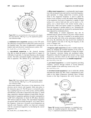
An inverted-coaxial magnetron is one in which the cathode
surrounds the anode (Fig. M3). Such a configuration is pref-
erable at the higher frequencies (typically above X-band)
because at the high frequencies the cavity becomes very
Figure M2 Cross-sectional sketch of classical cavity magne-
tron (from Skolnik, 1980, Fig. 6.1, p. 193, reprinted by permis-
sion of McGraw-Hill).
oxide-coated material. The process of the interaction of the
electrons and dc electric and magnetic fields takes place in
the interaction space (5). The RF power is extracted by plac-
ing a coupling loop (6) in one of the cavities, and the stability
and efficiency of the tube is improved by the straps (7): metal
rings connected to alternate segment of anode block. The pre-
ferred mode of magnetron operation (p-mode) corresponds to
an RF field configuration in which the RF phase alternates
180° between adjacent cavities. The conventional magnetron
can operate rather successfully through X- or K -band. Above
u
this frequency, rising-sun or inverted coaxial magnetrons are
typically used. Frequency stability was improved, compared
with the conventional magnetron, by developing the coaxial Figure M3 Inverted coaxial magnetron: (a) simplified cross-
magnetron. SAL section; (b) simplified perspective (from Skolnik, 1990, Fig.
Ref.: Ewell (1981), p. 22; Skolnik (1980), p. 192. 4.5, p. 4.7, reprinted by permission of McGraw-Hill).