
Page 274 - Radar Technology Encyclopedia
P. 274
matrix, multiport MEASUREMENT, radar 264
might be various electrical values: normalized (with dimen- ·
sionality of the square root of watts) voltages, currents enter- · = u om
---------
s mn ·
ing the multiport, normalized voltages of incident and u in ·
,
u iq = 0 q , = 1 N q ¹, n
reflected waves. This determines the many mutually related
matrices of a multiport, each of which is a complete external Elements of the scattering matrix are nondimensional:
characteristic, since it makes it possible to calculate the reac- the diagonal elements are the reflection factors for each input
tion to any external action. Three types of matrices have spe- of a multiport with matched loads at the inputs. IAM
cial uses: the conductance matrix, the impedance matrix, and Ref.: Gardiol (1984), p. 238; Sazonov (1980), p.72.
the scattering matrix. The last is introduced analogous to the
MAXWELL’S EQUATIONS (see WAVE, electromag-
radar scattering matrix in the form of the relation of reflected
netic).
and incident waves.
The matrix determines the behavior of a multiport only at MEASUREMENT, radar. Radar measurement is the pro-
a given frequency of oscillations. In the description of behav- cess of estimating target parameters, typically the angular
ior of a multiport in the frequency band, the elements of any coordinates q (azimuth and elevation); range R; radial veloc-
of its matrixes are converted to complex frequency functions. ity v ; and radar cross section s. Information on these param-
r
IAM eters is coded in the spatial and temporal structure of the echo
Ref.: Sazonov (1988), p. 78. signal y(t), which can be represented as
The polarization scattering matrix S, is the 2-by-2 matrix y pt ,( ) y pt ,( ) nt ()
=
+
s
that relates the vector components of the scattered field E s where y pt ,( )
and n(t) are samples of the useful signal and
s
and the incident field E : noise, respectively, p = ( q t f A,)
r
is the vector of mea-
,,
E = SE d d
s r sured parameters, q is the angular coordinate, t is time delay
d
The components of these field vectors are complex num- (proportional to R), f is doppler frequency (proportional to
d
bers and describe the components of the scattered and inci- v ), and A is signal amplitude (proportional to s ). The for-
r
dent waves in some polarization basis. The elements of the malized representation of the radar measurement task is then
ˆ
scattering matrix are complex numbers which depend on the to find an estimate p of vector p with minimum error d p ,
angle of incidence of the wave at the target, the angle of based on the received sample, y pt ,( )
. Because the received
observation, and the distance between the antenna and the tar- signal is corrupted by random interference (noise, jamming,
get. The scattering matrix is a complete characterization of clutter, or their combinations), the radar measurement if a sta-
the scattering properties of the target, inasmuch as it may be tistical process and is based on methods of statistical mea-
used to determine the amplitude, phase, and polarization of surement theory. The best developed theory is for
each spectral component of the scattered wave, for a given measurement in white, Gaussian noise (see SIGNAL param-
illuminating field. The matrix derived in this fashion is the eter estimation).
bistatic scattering matrix. In the particular case of backscat- The main parameter describing the quality of radar mea-
tering, the matrix is called the monostatic scattering matrix, surement is the accuracy, defined by the value of errors (see
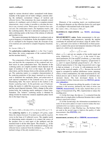
and has equal diagonal elements. With a change in the polar- ERROR, measurement). In the radar channel there are two
ization basis, the scattering matrix undergoes a linear trans- stages of measurement (Fig. M8), implemented to reduce the
formation. The “relative” scattering matrix is obtained by resulting error:
taking outside the matrix the common amplitude-phase factor (1) At the first stage, the data on p is extracted from the
due to the target range R : radar echo of a single pulse (in Russian literature this is called
0
R primary signal processing);
æ 0 ö
exp j2p ------
è l ø (2) At the second stage, the information accumulated in a
------------------------------ series of successive pulses or scans is used to reduce the mea-
4pR
0
surement error (secondary signal processing).
IAM Different methods of data filtering (e.g., the Kalman filter)
Ref.: Tuchkov (1985), p. 48; Kobak (1975), p. 48; Knott (1993), pp. 71–74. are used at the second stage to improve the quality of radar
The scattering matrix S, of a multiport (2N ports), estab- measurement. (See FILTER.) SAL
lishes the relation between N incident waves and the reaction Ref.: Barton (1969).
vector in the form of N reflected waves. The simplest mode measurement, accuracy of (see ERROR, measurement).
for determining matrix elements is to connect the source of
the incident wave to each input of the multiport and the Stage I Stage II
·
matched loads to all the other inputs. The element s mn of the
y( p, t) Plot p
matrix S is equal to the ratio of the normalized voltages of the Tracker
· extractor
reflected waves scattered from the multiport u om , to the nor-
·
malized voltage of the only incident wave u in :
Figure M8 Two stages of radar measurement.