
Page 271 - Radar Technology Encyclopedia
P. 271
261 magnetron, spin-tuned magnetron, voltage-tunable
these crystals it can cause the change in cavity tuning. There
are major difficulties in practical implementation of elec-
tronic tuning at high power levels, so satisfactory operation
typically can be achieved only at modest power levels. The
typical example of devices implementing electronic tuning
are multipactor-tuned magnetrons.
Mechanical tuning uses tuning elements, such as rods or
rings, which are inserted into the holes of resonators to
change the inductance of the resonant circuit. These elements
can move in a reciprocating or rotatory manner. Most of the
readily available devices used in radar systems use the
Figure M5 Rising-sun magnetron configuration (from
approach based on inserting some structures within the cavity
Skolnik, 1980, Fig. 6.2b, p. 194, reprinted by permission of
and their motion inside it to tune the magnetron. The main
McGraw-Hill).
techniques to implement mechanical tuning are rotatory (or
the slotted disk that is suspended above the anode resonators
spin) tuning (see spin-tuned magnetron), dither-tuning (see
(Fig. M6). Rotation of this disk provides inductive or capaci-
dither-tuned magnetron), and gyro-tuning (see gyro-tuned
tive loading of the resonators, the frequency changing up or
magnetron). Mechanical tuning over a 5 to 10% frequency
down, respectively. This technique was developed around
range is typical (in some cases as much as 25% can be
1960 was one of the first for achieving frequency agility in
achieved).
magnetrons. Very fast tuning rates are feasible, but when
The comparison of a number of different techniques to
used for MTI radars stability is lower than with other tuners.
arrange the tuning in medium power K -band magnetrons are
u
SAL
given in the Table M2. SAL
Ref.: Skolnik (1980), p. 199; Skolnik (1990), p. 4.6; Fink (1975), p. 9.53.
Ref.: Ewell (1981), pp. 26–33; Skolnik (1980), p. 199.
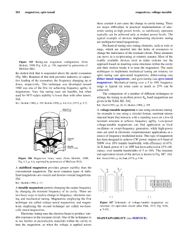
A voltage-tunable magnetron is one using electronic tuning.
An example is one using a circular-format, reentrant-stream
injected beam that interacts with a standing wave on a low-Q
resonant structure to achieve frequency agility. Low-power
voltage-tunable magnetrons can find application as local
oscillators or swept-frequency generators, while high-power
ones are used in electronic countermeasure applications as a
source of frequency-modulated noise. This type of magnetron
has been designed to achieve CW power outputs at S-band of
500W over 10% tunable bandwidth, with efficiency of 65%.
At X-band, power of 1 to 10W has been achieved at 25% effi-
ciency, over tunable bandwidths of 5 to 10%. The structure
and equivalent circuit of the device is shown in Fig. M7. SAL
Figure M6 Magnetron rotary tuner (from Skolnik, 1990, Ref.: Ewell (1981), p. 26; Fink (1975), p. 9.54.
Fig. 4.3, p. 4.6, reprinted by permission of McGraw-Hill).
Accelerator
A stabilized magnetron provides greater stability than the Cathode electrode
conventional magnetron. The most common types of stabi- Anode: low-Q
resonant circuit
lized magnetrons are coaxial and inverse-coaxial magnetrons.
SAL
Ref.: Skolnik (1990), p. 4.7.
Sole L R
A tunable magnetron permits changing the output frequency
by changing the resonant frequency of its cavity. There are
two basic ways to realize change in frequency: electronic tun-
(a) (b)
ing and mechanical tuning. Magnetrons employing the first
technique are called voltage-tuned magnetrons and magne- Figure M7 Schematic of voltage-tunable magnetron: (a)
trons employing the second technique are called mechani- structure; (b) equivalent circuit (after Fink, 1975, Fig. 9-66,
cally-tuned magnetrons. p. 9-54).
Electronic tuning uses the electron beam to produce vari-
able reactance in the resonant circuit. One of the techniques is MAINTAINABILITY (see SERVICE).
to use ferrites or piezoelectric materials within the cavity to
tune the magnetron, as when the voltage is applied across