
Page 270 - Radar Technology Encyclopedia
P. 270
magnetron, inverted-coaxial magnetron, spin-tuned 260
small, so the usual construction would leave inadequate room quency tuning and the use of frequencies over a wide band.
for the anode and cathode structure. Sometimes this structure However, they do not provide coherence from pulse to pulse,
is also called an inverted magnetron. SAL have low frequency stability and a comparatively high power
Ref.: Skolnik (1990), p. 4.7. of parasitic radiation.
This device is also called a multicavity, multicircuit, or
mechanically-tuned magnetron (see tunable magnetron).
multisectional magnetron. IAM
A multipactor-tuned magnetron uses the effect of a multi- Ref.: Gilmour (1986), p. 352; Leonov (1988), pp. 45, 46; Andrushko (1981),
pactor discharge to vary the frequency of an auxiliary coupled p. 81.
resonator, which in turn changes the magnetron operation fre-
A pulsed magnetron is one operating in a pulsed mode.
quency. Each auxiliary cavity is coupled to a given anode and
Pulsed modulation typically is obtained by applying a nega-
can be turned on or off independently, so in general 2n com-
tive rectangular voltage pulse to the cathode with the anode at
binations of frequencies may be selected, where n is a number
ground potential. The devices have been developed covering
of cavities. SAL
frequency ranges from a few hundred megahertz to 100 GHz,
Ref.: Ewell (1981), p. 28.
the peak power up to several megawatts, the efficiency is
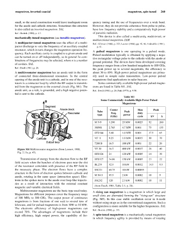
A multiresonator magnetron has an anode unit in the form about 30 to 40%. High-power pulsed magnetrons are prima-
of connected three-dimensional resonators. In the central rily used in simple radar transmitters. Low-power pulsed
opening of the anode unit is a cathode, and in one of the reso- magnetrons find applications in radar beacons.
nators is a connector loop by which the RF output is transmit- Some commercially available high-power pulsed magne-
ted from the magnetron to the external circuit (Fig. M4). The trons are listed in Table M1. SAL
anode unit, as a rule, is grounded, and a high negative poten- Ref.: Ewell (1981), p. 28; Fink (1975), p. 9.50.
tial is sent to the cathode.
Table M1
Some Commercially Available High-Power Pulsed
Magnetrons
Center Max Peak
Tube freq. Peak duty
type power
(GHz) cycle kV A
M 545 1.290 25 MW 0.0025 52 260
3M901 2.765 4.7 MW 0.001 75 135
SFD344 5.60 1.0 MW 0.001 37.5 65
VF 11 9.25 1.0 MW 0.0015 30 70
7208 B 16.5 100 kW 0.001 22 20
Figure M4 Multiresonator magnetron (from Leonov, 1988, VF 20 16.5 400 kW 0.0015 26 40
Fig. 2.11a, p. 45).
SFD326 24 120 kW 0.0005 14 30
Transmission of energy from the electron flow to the RF SFD327 34.86 150 kW 0.0005 23 22
field occurs when the bunches of electrons pass near the slot
BL235 52.5 10 kW 0.0012 14.5 9.5
of the resonator coincident with presence of the RF field in
the necessary phase. The electron flows have a complex DX221 69.75 10 kW 0.00055
structure in the form of electron spokes between cathode and
M 5613 95.5 2 kW 0.0002 10 9
anode, rotating in the same space (interaction space). Elec-
trons in the spokes move to the anode over loop-like trajecto- DX252 120 2.5 kW 0.0002 10 11
ries as a result of interaction with the external constant
(from Ewell, 1981, Table 2-1, p. 28).
magnetic and variable electrical fields.
Multiresonator magnetrons are the basic type used today.
A rising sun magnetron is a magnetron in which large and
Magnetrons for different purposes cover the frequency range
small slots are alternated forming the “rising-sun” structure
of 300 MHz to 300 GHz. The output power of continuous
(Fig. M5). In this case stable oscillation occur in p-mode
magnetrons is from fractions of one watt to several tens of
without using straps as in the conventional magnetron. Such a
kilowatts, and for pulsed magnetrons is from 10W to 10 MW.
configuration is more suitable for the higher frequencies. SAL
The electronic efficiency of high-power magnetrons can
Ref.: Skolnik (1980), p. 193.
exceed 70%. The advantages of magnetrons include their
high efficiency, high output power, the capability of fre- A spin-tuned magnetron is a mechanically tuned magnetron
in which frequency agility is provided by means of rotating