Page 263 - Radar Technology Encyclopedia
P. 263

253   loss, field degradation                                                           loss, fluctuation


           subjective estimation of the quality of maintenance personnel,  Filter straddling loss results from the use of a fixed doppler
           or by flight testing. DKB                            filter bank to process signals from targets having arbitrary
                                                                doppler shifts, some of which fall in regions having response
           Filter matching loss results  from departure  of the  actual
                                                                lower than the maximum. It is defined as the increase in sig-
           receiver filter  from the  matched filter for the transmitted
                                                                nal energy required to achieve given probability of detection
           waveform, on a single-pulse basis. It is defined as the ratio of
                                                                for target doppler shifts uniformly distributed over the filter
           receiver output signal-to-noise ratio to that available from a
                                                                bank response, compared with a target centered in a doppler
           filter matched to the individual pulse. For simple rectangular
                                                                filter. The loss is minimized by use of closely spaced filters,
           pulses  (having no phase  modulation),  the loss for different
                                                                such as those formed in an FFT filter bank when low-sidelobe
           types of filter is shown in Fig. L25. For linear-FM pulse com-
                                                                weighting is used, or use of zero-padding of the FFT input (a
           pression signals, the loss as a function of sidelobe level, for
                                                                process that adds strings of zeroes at each end of the n-pulse
           different families of weighting function, is identical to that for
                                                                data sample, decreasing the filter spacing while leaving the
           doppler filters, shown in Fig. L10. DKB
                                                                filter bandwidth constant).
           Ref.: Barton (1969), pp. 56, 84.
                                                                    An approximation for L  is
                                                                                       ef
                                                                                        1
                                                                                        -- -  2
                                                                                         æ
                                                                                          -------    (dB)
                                                                               L  =  1.25P 3 Df   ö
                                                                                ef      d è B ø
                                                                                           f
                                                                where D is the filter spacing, B  is filter bandwidth, and P  is
                                                                       f
                                                                                         f
                                                                                                              d
                                                                   detection probability. For the FFT processor, Df/Bf = 1/t f
                                                                   B , and the straddling loss will be a function of the weight-
                                                                    f
                                                                   ing function (Table L11) DKB
                                                                Barton (1993), p. 133.
                                                                                     Table L11
                                                                         Bandwidth Constants for Weighted FFT
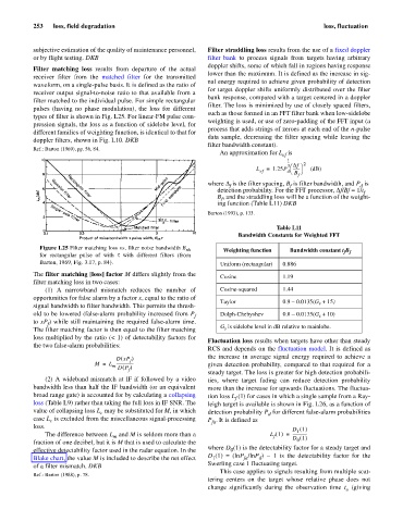
             Figure L25 Filter matching loss vs. filter noise bandwidth B nh  Weighting function  Bandwidth constant t B
             for  rectangular pulse of  with  t  with  different filters (from                           f f
             Barton, 1969, Fig. 3.17, p. 84).                       Uniform (rectangular)  0.886
           The filter matching [loss] factor M differs slightly from the  Cosine       1.19
           filter matching loss in two cases:
               (1) A narrowband  mismatch reduces the number of     Cosine-squared     1.44
           opportunities for false alarm by a factor x, equal to the ratio of
                                                                    Taylor             0.9 -  0.0135(G  + 15)
                                                                                                  s
           signal bandwidth to filter bandwidth. This permits the thresh-
           old to be lowered (false-alarm probability increased from P f  Dolph-Chebyshev  0.8 -  0.0135(G  + 10)
                                                                                                  s
           to xP ) while still maintaining the required false-alarm time.
               f
           The filter matching factor is then equal to the filter matching  G  is sidelobe level in dB relative to mainlobe.
                                                                     s
           loss multiplied by the ratio (< 1) of detectability factors for
                                                                Fluctuation loss results when targets have other than steady
           the two false-alarm probabilities:
                                                                RCS and depends on the fluctuation model. It is defined as
                                                                the increase in average signal energy required to achieve a
                                    DxP )
                                      (
                                        f
                              M =  L -----------------          given detection probability, compared to that required for a
                                   m
                                      (
                                     DP )
                                        f
                                                                steady target. The loss is greater for high detection probabili-
               (2) A wideband mismatch at IF if followed by a video  ties,  where target fading can reduce detection probability
           bandwidth less than half the IF bandwidth (or an equivalent  more than the increase for upwards fluctuations. The fluctua-
           broad range gate) is accounted for by calculating a collapsing  tion loss L (1) for cases in which a single sample from a Ray-
                                                                        f
           loss (Table L9) rather than taking the full loss in IF SNR. The  leigh target is available is shown in Fig. L26, as a function of
           value of collapsing loss L  may be substituted for M, in which  detection probability P  for different false-alarm probabilities
                               c
                                                                                  d
           case L  is excluded from the miscellaneous signal-processing  P . It is defined as
                c
                                                                 fa
           loss.
                                                                                          D 1 ()
                                                                                           1
                                                                                        =
               The difference between L  and M is seldom more than a               L 1 () ---------------
                                   m
                                                                                    f
                                                                                           0
           fraction of one decibel, but it is M that is used to calculate the             D 1 ()
           effective detectability factor used in the radar equation. In the  where D (1) is the detectability factor for a steady target and
                                                                       0
           Blake chart, the value M is included to describe the net effect  D (1) = (lnP /lnP )  - 1 is the  detectability factor for the
                                                                  1
                                                                                d
                                                                           fa
           of a filter mismatch. DKB                            Swerling case 1 fluctuating target.
                                                                    This case applies to signals resulting from multiple scat-
           Ref.: Barton (1988), p. 78.
                                                                tering centers on the target whose relative phase does not
                                                                change significantly during the  observation time  t  (giving
                                                                                                          o
   258   259   260   261   262   263   264   265   266   267   268