
Page 248 - Radar Technology Encyclopedia
P. 248
LIMITER limiter, diode 238
LIMITER. A limiter is a “transducer whose output is con- to compress the dynamic range of signals, and in receiver pro-
stant for all inputs above a critical value.” It is used to limit tectors as solid-state replacements for or supplements to gas-
both RF and video pulse amplitudes. Based on type of active tube or circulator-type duplexers.
element, they are subdivided into diode and transistor limit- The operating principle of a diode limiter is based on the
ers. Transistor limiters are usually used as controllable micro- change in resistance of the diode. Depending on whether the
wave amplifier-limiters. IAM diode is connected in serial or parallel relative to the load
Ref.: IEEE (1993), p. 716; Gassanov (1988), pp. 135, 142, 143; Skolnik resistance, the diode limiter is called a serial or parallel lim-
(1990), p. 3.30. iter. The choice is determined by the load resistance (serial
An avalanche-multiplying limiter is an uncontrolled power limiters should be connected to circuits with a low output
limiter based on avalanche microwave breakdown in the resistance), and by the type of microwave transmission line.
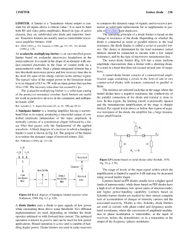
semiconductor. It is made in the shape of an element with sur- The series-diode limiter (Fig. L9) has a more uniform
face-oriented electrodes in the form of counter-teeth on a amplitude characteristic than a limiter with a shunting diode.
semiconductor wafer. Such a planar-integrated element has a It is used in a band that does not exceed several tens of mega-
low threshold microwave power and low recovery time due to hertz.
the short life span of the charge carriers in the surface region. A tunnel diode limiter consists of a transistorized ampli-
The typical value of the output power in the limitation mode fication stage containing a circuit in the form of one or two
is in an integral of 0.5 to 1W with an input power that reaches counter-serial diodes with resistors connected in parallel to
10 to 15W. The recovery time does not exceed 0.1 ms. them.
The avalanche-multiplying limiter is a solid-state analog The resistors are selected such that in the range where the
of the protective resonance crowbar. Such limiters are useful tunnel diodes have a negative resistance, the conductivity of
for work in protective devices in the centimeter and millime- the parallel connection of the diode and resistor is close to
ter bands. IAM zero. In this region, the limiting circuit is practically opened
and the instantaneous amplification of the stage is sharply
Ref.: Lebedev, I. V., Radioelektronika 33, no. 10, 1990, pp. 58–61.
limited. For signal levels above or below this region of nega-
A bandpass limiter is a limiting amplifier having a narrow-
tive resistance of the diode, the amplifier has a large instanta-
band filter at its output, producing a sinusoidal output of con-
neous amplification.
trolled amplitude independent of the input amplitude. It
normally consists of a symmetrical clipper followed by a lin-
ear filter that passes only the fundamental of the applied
waveform. A block diagram of a receiver in which a bandpass
limiter is used is shown in Fig. L8. The purpose of the limiter
is to reduce the dynamic range of received echoes. SAL
Ref.: Nathanson (1969), pp. 119–130.
s (t)
2
s (t) n (t)
1
1
Threshold
Figure L9 Limiter based on serial diodes (after Skolnik, 1970,
S
Fig. 33, p. 5.38).
Detector
Ideal limiter The range of levels of the input signal within which the
amplification is limited is equal to 6 dB and may be increased
Input Output Matched
bandpass bandpass using several limiter stages.
filter filter filter Limiters based on PN diodes usually have a higher speed
(units of nanoseconds), while those based on PIN diodes have
a high level of limitation, low speed (units of microseconds),
and higher power-handling capability. Limiters based on
Figure L8 Block diagram of bandpass limited receiver (after Schottky-barrier diodes are marked by their almost complete
Nathanson, 1969, Fig. 4.5, p. 120).
lack of accumulation of charges of minority carriers and the
associated reactivity. Thanks to this, Schottky diode limiters
A diode limiter uses a diode to pass signals of low power
are used in circuits with phase-coded and frequency-modu-
while attenuating those above some threshold. Two different
lated waveforms, where the conversion of amplitude modula-
implementations are used, depending on whether the diode
tion to phase modulation is undesirable; at the input of
operates unbiased or with forward-bias current. The unbiased
receivers, before the demodulator; or in a transmitter at the
operation is known as passive and can be used for low-power
output of the frequency (phase) modulator.
applications. Biased operation is active and is capable of han-
dling higher power. Diode limiters are used in radar receivers